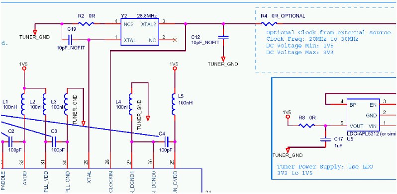
Stock Elonics E4000 Schematic
Mirrored from: GBPPR 'Zine - Issue #104
|
Overview
Most Realtek RTL2832 / Elonics E4000-based tuners use a 28.8 MHz crystal for generating the Phase Lock Loop's (PLL) reference frequency. Ideally, this 28.8 MHz reference frequency should be very stable and with low phase noise. Because these USB tuners were designed to be low cost, they'll often skip on the quality of the crystal used for this frequency. This can result in alot of frequency drift, which you'll notice when operating the tuners in narrowband modes.
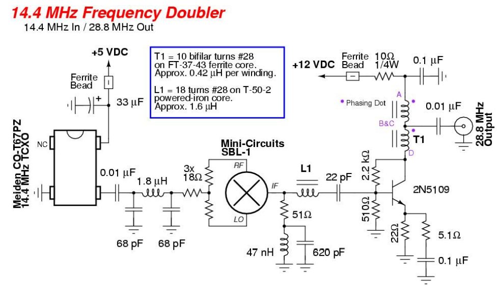
While a high-quality standalone 28.8 MHz Temperature-Compensated Crystal Oscillator (TCXO) may be difficult to track down, 14.4 MHz TCXOs are actually quite common. By feeding a 14.4 MHz signal into a "frequency doubling" circuit, we can then generate a "new" reference frequency at 28.8 MHz.
The 14.4 MHz TCXO used for this project is a Meiden CO-T67PZ oscillator. It runs at +5 VDC and generates an approximate 400 mVp-p clipped sine wave output signal with its phase noise -140 dBc at a 10 kHz offset. You can purchase these Meiden oscillators via eBay, or similar oscillators may be salvaged from certain Motorola two-way radios.
A Mini-Circuits SBL-1 double-balanced mixer will be used in a passive "frequency doubler" application. The incoming 14.4 MHz will be split in two and fed to the LO and RF ports on the SBL-1. The doubled output at 28.8 MHz will then be taken via the mixer's IF port. A standard diplexer network and 2N5109 post-mixer amplifier is then used to isolate and amplify the 28.8 MHz signal.
Stock Elonics E4000 Schematic
Pictures & Construction Notes
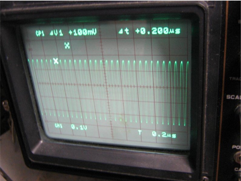
Output view of a stock Meiden CO-T67PZ 14.4 MHz TCXO.
100 mV per division vertical / 0.2 µS per division horizontal.
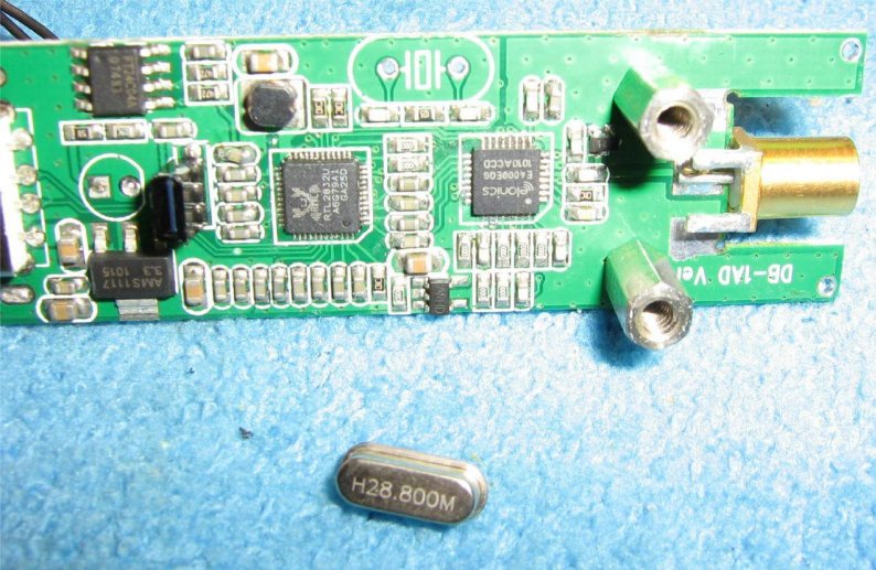
Removing the stock 28.8 MHz crystal on a Realtek RTL2832 / Elonics E4000-based tuner.
Save this crystal, as it may be possible in a future project to turn it into a crystal filter to further clean up the reference signal's phase noise.
It's not necessary to remove any of the crystal's loading capacitors.
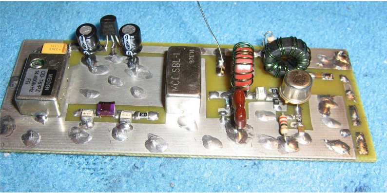
Overview of the passive frequency doubler circuit board.
This project is still experimental and should be considered a work-in-progress.
The Meiden CO-T67PZ 14.4 MHz TCXO is on the left, the Mini-Circuits SBL-1 is in the middle, and the 2N5109 post-mixer amplifier is on the right.
A simple 3-pole low-pass / impedance matching network cleans up the 14.4 MHz signal before a passive resistive divider network splits the signal for the SBL-1's RF and LO ports.
On the IF output of the SBL-1 mixer is a LC diplexer network and a 2N5109 transistor-based amplifier. This is a bit of overkill, but it works.
The frequency doubler circuit does require +12 VDC to operate. You'll want to run the USB tuner from an external linear DC power supply for maximum performance anyway, so it's not that big of a deal.
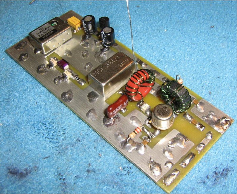
Alternate view.
The IF output of the SBL-1 passes through the LC diplexer network to isolate the 28.8 MHz signal and shunt the out-of-band signals to a 50 ohm load. This helps the mixer "see" a 50 ohm impedance at all the mixed frequencies to reduce any distortion.
The 2N5109 transistor provides around 20 dB of gain to overcome all the losses which results from the passive frequency doubling action.
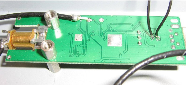
Applying the new 28.8 MHz signal to the USB tuner.
Shown above is the bottom of the Realtek RTL2832 / Elonics E4000-based tuner, with the antenna input on the left.
The signal should be applied directly to pin 29 of the Elonics E4000. You may want to trace this out with a meter before hand.
Experimentation showed the Elonics E4000 tuner requires a 28.8 MHz reference signal at around 0 dBm.