Solar Polarimeter
I would like to make a polarimeter to observe the sun and specifically the zeeman lande g = 3 splitting of Infrared line of Fe I, 15648.5 Angstrom, e^7 D_1 transition to 3d^6 4s 5p^7 D[0,1] where the longitudinal field is, B(gauss) = (2.86*10^4)* delta_λ(nm shifted from line center)). This line is fully resolved since the Zeeman shift is larger than the Doppler line width, at least in sunspots. But I doubt I can ever build a filter, or grating based spectrograph, with such fine spectral resolution. Instead just plain polarimetry can be informative.
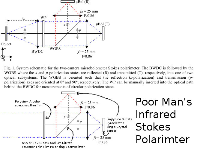
I will use the general theory from "Infrared Stokes imaging polarimeter using microbolometers" except to use stretched thin film polyvinyl alcohol for the quarter waveplate, replace the wire grid beamsplitter with a sodium nitrate capillary crystal in between two BK7 glass prisms as a Feussner polarizing beamsplitter, replace the microbolometer arrays with 2 single pixel 'camera' made from grown triglycine sulfate crystals, and the solid lenses with mechanical-wetting lenses of near-IR transparent fluids. This page is to document the theory and processes required to physically manufacture these alternatives parts instead of spending thousands of dollars buying the normal ones.
- Unsolved Prefilter Problems
- Design Overview and Obtaining Stokes Vector
- Stretched Polyvinyl Alcohol Waveplate Manufacture
- Sodium Nitrate Crystal Growth for Polarizing Beamsplitter
- Triglycine Sulfate Pyroelectric Detector Single Crystal Growth
- Manufacture of Mechanical-Wetting Liquid Lenses for Near-IR
- Optical Alignment with Cylinders in "V"s
The first and most serious problem is filtering for the desired wavelength. Triglycine sulfate crystals are very broadband. The first step would be a high-pass pre-filter to get rid of non-IR light. The second would be a specialized filter of some kind. It has become obvious the precision required for a Fabry-Perot interferometer to select wavelength is beyond my skill. But a lyot filter will require a lot of sodium nitrate plates as well as some KDP plates in complex arrangements and stacking with precision thicknesses. And KDP barely includes the Fe I line in it's transmission range of 174 to 1570 nm. But it's still slightly more feasible (less precision required) than making an F-P filter. Unfortunately the lyot filters' multiple polarizing elements destroy the original polarization leaving only a 45° linear beam. How else can the light be filtered to only pass a small line without fucking up the polarization? I am guessing only a custom order multilayer dialectric interference filter with light normal to it will work.
So far I have not solved this problem and the only solution seems to be buying a very expensive custom interference filter... who's off axis polarimetric effects I do not understand.
But disregarding that problem and moving on to the the polarimetric analyzer, a single Feussner polarizing beamsplitter of sodium nitrate within bought BK7 glass prism elements will be rotated. After 2 measurements by the two 'camera'/TGS crystals one stokes parameter should be found. This is described in the paper linked at the top as the below,
"In order to perform the various measurements corresponding to S1, S2, and S3, the analyzers must be altered. For S1, the polarizing beamsplitter is oriented with its reflection axis at 0° and transmission axis at 90°, providing a measurement of the horizontal and vertical intensities I_H and I_V, respectively. For S2, the beamsplitter is rotated by -45°, providing measurements of I_135 and I_45 in reflection and transmission, respectively. Lastly, for S3, the beamsplitter is oriented identically to the S1 configuration, but a form-birefringent wave plate (WP), oriented at 45°, is inserted into the optical path behind the focusing lens. If the WP has a retardance of 90°, then measurements of I_R and I_L are obtained. However, since the retardance of the WP is actually 85.8 degrees, uncertainty is contributed to the measurement of I_R and I_L at spatial locations where S1 is present. The error, ε, depends on the ratio of S1 to S3,"
Assuming all the optics issues are solved then a detector is still needed. If I use a very small, cooled, triglycine sulfate (TGS) pyroelectric crystal who's optical path is mechanically chopped/interrupted then when I measure the crystal surface face voltages along the ferroelectric monoclinic b-axis it should give relative intensities. Subtract the voltage during dark times from when the crystal is exposed to the light to find intensity from the light source. TGS should have a ~90% transmission in the wavelength range of 200-1100nm, so in a way it acts as it's own filter. The voltages induced on the surface of the crystal will probably be very small, on the order of millivolts, and the differences in the voltages between polarization states even smaller (microvolts). I plan to use the direct sampling mode of the rtl-sdr software with a DVB usb dongle with the RTL2832U chip. These are sensitive down to ~0.3 microvolt and take 8bit IQ samples at up to 2.4 MS/s.
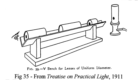
For optical alignment use "Cylinders in Vs, An optomechanical methodology", "More Cylinders in Vs_ Optomechanics_ Douglas S Goodman_ 2001" , which is basically how it sounds. A "V" shape in which cylinders can be placed in repeatable optical alignment. Seems pretty cheap and feasible to implement on a low budget. It's just some pipe and angle aluminum... and of course 3 point screws to hold the optical elements.
Manufacture of Polyvinyl Alcohol Waveplates
Edit, Sat Dec 3rd, 2011: It turns out there is a way to home manufacture zero order waveplates for the near infrared afterall. I stumbled upon the amazing paper by Dongguang Wanga, Yuanyong Denga, and Wenda Cao called, "Near Infrared Waveplate" which describes the optical properties and some of the manufacturing technique for zero-order waveplates exactly at the ~1560nm wavelength with the intended use for stokes polarimetry! The paper is well worth a read, but the gist is that the harmless and cheap polymer Polyvinyl Alcohol (PVA) in the form of thin film that has been stretched in one direction makes a perfect waveplate with a flat spectral response. In order to manufacture a specific thickness of PVA the best method I could think of was spin coating, where a solution of PVA in water is dripped onto a rapidly rotating glass substrate. For low concentrations (under 5% PVA) the thickness is a linear function of rotation rate. A low cost homemade spin coater can easily be assembled with a DVD spindle motor (which takes plain DC, speed proportional to voltage) and linear potentiometer. Thickness can be measured by the changing color of the spinning plate at an angle due to optical interference effects of the thin films' thickness (like a soap bubble). With this method thin films of only some microns in thickness can be made with a very even surface. This would then be carefully heated, stretched and measured the same wave to achieve the desired thickness for zero-order 1/4, 1/2, etc waveplates. The slow axis will be in the direction of stretch. With this there is no more need to grow KDP crystals and tune! The problems with this are the water vapor sensitivity and mechanical fragility. The think film would have to be protected by encasing it within BK7 glass plates.

"1%, 2% and 5% (w/v) polymer solutions of PVA were made by heating distilled (DI) water to 85°C and adding PVA one gram at a time until all was dissolved. The solution was brought up to its correct volume, sealed and left to stir overnight. The next day, the solution was vacuum filtered... A PVA film was fabricated by dropping PVA solution on glass substrates and drying. The birefringence in a PVA film is induced in proportion to the film stretching. The film which was exfoliated from the glass substrates was extended by the drawing machine. It was heated by the warm wind in order to stretch a film over 70C which is glass transition temperature of PVA. The stretching speed was about 5mm/sec, and the stretching ratio of the sample was set at 1, 3, and 5 times...Thus, the 2% polymer was found to be the most ideal concentration to use, while 2000 RPM was found to be the best spin speed to create the least number of imperfections." -- Optimization of Step and Flash Imprint Lithography: Imprinting a Substrate for One Step Release of Drug Delivery Nanocarriers
Sodium Nitrate Optical Crystal Growth for Polarizing Beamsplitter
Since 6400 cm^-1 =~ 1563 nm, the trend looks like sodium nitrate will be ~80% transmittance at the required wavelength. Older studies show absorbances as low as 30% at ~1-2 micron as in "The infrared absorption spectra of sodium nitrate and calcite_ A K Ramdas_ 1953". And given only a thin film will be used, absorption should not be a problem.
Grow Sodium Nitrate birefringent crystals on cleaved mica. Use these to make thin film polarizing beamsplitter. The birefringence index at a much shorter wavelength than in question is N_o 1.5854 , N_e 1.3369 , making it slightly better than calcite (1.6584,1.4864). I hoped to grow salt cubes to use for the right angle prisms, but it seems like it'd just be easier and safer to buy 2 BK7 glass prisms online (10mmx10mm ~ $20 to $50 each).
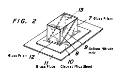
For the polarizing beamsplitters follow, "Manufacturing Method of the Sodium Nitrate Polarizers_ USP3075869" and there's no need to grow large crystals of sodium nitrate or to worry about alignment. Instead one just has to buy a couple BK7 glass prisms. Place the prism halves on a sheet of mica with a melt of sodium nitrate. The capillary flow of sodium nitrate between the prisms, during cooling of the mica from below, will be oriented such that a thin film single crystal of sodium nitrate is made with the optical axis normal to the mica surface. Tada, a polarizing beamsplitter with sodium nitrate protected by the prisms which are transparent to the far infrared. Water vapor in the air will be a problem, but not insurmountable. This would be a Feussner polarizing beamsplitter.

Quotes below from, chapter 13 of Handbook of Optics, "Polarizers" by Jean M Bennet.
"In essence, Feussner’s idea was to make the prisms isotropic and the film separating them birefringent, as shown in Fig. 12. The isotropic prisms should have the same refractive index as the higher index of the birefringent material so that for negative uniaxial materials e.g., calcite or sodium nitrate, the ordinary ray is transmitted and the extraordinary ray totally internally reflected. Advantages of this design are (1) since the ordinary ray is transmitted, the refractive index does not vary with angle of incidence and hence the image is anastigmatic, (2) large field angles or prisms of compact size can be obtained, and (3) the bire- fringent material is used economically. Furthermore, because the path length of the ray through the birefringent material is short, a lower-quality material can be used."
"Disadvantages are (1) for both calcite and sodium nitrate, the extraordinary ray is transmitted over a larger wavelength range than the ordinary ray so that Feussner prisms do not transmit over as large a wavelength range as conventional prisms, and (2) the thermal-expansion coefficients of the isotropic and birefringent materials are different, making thermally induced strains likely. Solutions to the second problem are to use a thixotropic cement, which flows more readily with increasing stress, or to enclose the system in a metal sleeve and use oil instead of cement. If the ordinary index is matched by the oil, the birefringent material does not even need to be polished very well. Even a cleavage section of calcite can be used, with only a tolerable loss in angular field."
"Since sodium nitrate is easily obtainable and has a birefringence even larger than that of calcite, attempts have been made to produce polarizing prisms of this material by Wulff, Stöber, Tzekhovitzer, West, Huot de Longchamp, and Yamaguti. However, it is not only deliquescent but also very soft, so that although large single crystals can be obtained, they are difficult to work. They can be crystallized in the desired orientation from a melt using a technique discovered by West. When sodium nitrate crystallizes from a melt on a mica cleavage surface, one of its basal planes is oriented parallel to the mica cleavage and hence its optic axis is perpendicular to themica surface. West reports growing single crystals as large as 38 × 19 × 2 cm using this technique. Yamaguti has produced polarizing prisms of sodium nitrate by placing thin, closely spaced glass plates on edge on a mica sheet and then immersing the assembly in a melt of sodium nitrate. The thin single crystal thus formed was annealed and cemented between glass prisms to form a Bertrand-type Feussner prism. Conceivably, the sodium nitrate could have been grown directly between the glass prisms themselves, but when such thick pieces of glass are used, it is difficult to avoid setting up strains in the crystal and consequently reducing the polarization ratio. Yamaguti used SK5 glass prisms (nD = 1.5889) cut at an angle of 23° to form his polarizing prism and reports a field of view of 31°, symmetric about the normal to the entrance face."

Glass types and their refractive indices from refractiveindex.info:
BK7,BSC7,BSL7 @ 1560nm = 1.50053
reflectance @ 23° = S(0.049713), P(0.031385)
reflectance @ 45° = S(0.092138), P(0.0084895)
reflectance @ 67° = S(0.25409), P(0.021855)

SK5,BaCD5,BAL35 @ 1560nm = 1.57101
reflectance @ 23° = S(0.060591), P(0.039111)
reflectance @ 45° = S(0.10874), P(0.011824)
reflectance @ 67° = S(0.28124), P(0.019040)
http://www.emsdiasum.com/microscopy/products/preparation/mica.aspx has cheap, high surface quality mica sheets @ $1.25 each for the required sizes.
Triglycine Sulfate detector single crystal growth...

In the past I have used battery grade sulfuric acid and reagent grade glycine powder which is heated above 60C. I then slowly lowered the temperature of the covered solution on the stirring hotplate over a day to 35C, where the above solution would be just barely supersaturated. The solution was then put onto a large pan and evaporated for (crappy) seed crystals and purification. For references about how to perform this process and what ratios to use I read the invaluable, "Pyroelecticity: Triglycine sulfate crystal growth and characterization" by Yu Preezant and Y Preezant. and their lab write-up website at: http://physics.technion.ac.il/~jammia/advlab/advlab.htm
That made small seed crystals. To grow larger single crystal I am slowly implementing the design of a Sankaranarayanan-Ramasamy method crystallizer. I have bought and assembled a PID temperature controller with solid state relay and and platinum thermistor with 0.1C accuracy using the below listed parts.
http://www.lightobject.com/JLD612-Dual-Display-PID-Temperature-Controller-P43.aspx
http://www.lightobject.com/Water-resistant-PT100-RTD-01-degree-Sensor-Probe-P592.aspx
http://www.lightobject.com/25A-Solid-State-Relay-SSR-DC-In-AC-Out-P61.aspx
http://www.lightobject.com/Heat-sink-for-25A-SSR-P583.aspx
I also bought a number of 25 and 50ml conical glass centrifuge tubes to use as the actual crystallizer containers off Amazon.com: http://www.amazon.com/Centrifuge-Tube-Glass-Tapered-beaded/dp/B00187XOO8/ref=pd_sbs__1
I will use this 110VAC source to heat a stove heating element bent into a ring which is covered in epoxy to make it water tight. The temperature will never rise much above 35C so cracking will not be an issue. This temperature controller setup and heating element can than be used to replicate the S-R method as described in, "Growth of TGS crystals using uniaxially solution-crystallization method of Sankaranarayanan-Ramasamy". Seed crystals of defined faces will be selected from the first rapid drying process. The supersaturated solution will be prepared from the remaining marginal seed crystals and water for reasons of purification.
Using the S-R heater and crystallizer shape design with the crystallizer insultation design from Pyroelecticity_ Triglycine sulfate crystal growth and characterization, I should be able to grow properly oriented large single crystals from which to cleave and polish small mass slices to be used as detector elements.
Manufacture of Mechanical-Wetting Liquid Lenses
The solid lenses should be replaced with a mechanical-wetting lens of two immiscable liquids as in A novel adaptive mechanical-wetting lens for visible and near infrared imaging_ Su Xu_ Yifan Liu_ Hongwen Ren_ Shin-Tson Wu_ 2010.
The trick is to separate two fluids that do not mix (water and oil, etc), of approximately the same density, by a thin plate with a circular hole in the center. The two liquids form an meniscus interface at this hole with a shape defined by surface tension and pressure; it is a very, very smooth interface with little scattering. Lens power is altered in the same way as membrane lenses: by adjusting the relative pressure of the two liquids spherical deformations of the meniscus are induced. By selecting appropriate liquids (say, glycerol and SL-5267) you can get up to 1400nm transmission. And because there's no strain in the liquids there's no polarization effects. But unfortunately glycerol's IR cutoff does not extend to 1560nm, so an alternative must be found with the same density that is still immiscible.
Optical Alignment with Cylinders in "V"s
An aside on growing larger sodium nitrate crystals
For large single crystals of sodium nitrate instead of using capillary growth between prisms, follow the method of, "On the growth of large perfect crystals of sodium nitrate" S.N. Komnik, V.I. Startsev which takes it one step further.
"The production of sodium nitrate single crystals (with dislocation density of about 10^-5 cm-2) of 70 mm in diameter and 40 mm in length is described. The crystals were grown by the modified technique of Kyropulos , small plates of single crystal mica (of 20 mm in diameter) being used as a seed. The latter were glued to the cooler — a copper rod (water cooling was not needed). The growing of a crystal was accomplished in an aluminium crucible. The crystals obtained were completely transparent, without cracks, giving good cleavage planes. An etchant — zinc saturated ice acetic acid revealing both the grown-in dislocations and fresh one — is proposed."
Progress, 11/28/2011: PID heater and parts bought. Steel vacuum thermos bought. 6ft insulated heating wire bought.
Need to make a aluminum (NOT ALUMINA) crucible, as they say. I figure I'll use a steel one, the inside of a vacuum thermos as laid out in this excellent scientific american article: A Furnace in a Thermos_ Shawn Carlson_ Mar, 2000. The 340C needed for sodium nitrate will not stress it any. Heating rope can be bought from OMEGALUX Rope Heaters FGR-030. The furnace with it's steel of aluminum up does not seem hard. The 3ft would work for the sides and bits, but the always on bottom loop might require FGR-060 $29.00 6-Foot Length, 250 W, 120 V.
I bought 20x 18mm-diameter 1mm thick mica insulators with 6mm hole in center on ebay as diode insulators to use as a cover and window for the top of the furnance. I still need to buy proper quality muscovite mica sheets.

Crystal Growth
"To grow the crystal the crucible furnance of 120mm in diameter and 200mm in depth with the side and bottom heaters used. The bottom heater has a stabilized voltage. The power of the side heater is adjusted by potentiometer EPD-12 (see, avr? another temp controller). The thermocouple, placed neat the coild of the coil of the side of the heater, serves as a pickup. The furnace has a cover with two mica windows provided for visibility during growth. In the centre of the conver there is an opening for the cooler (coppper rod fixed to mica). The crystals were grown in an aluminium crucible of 100 mm in diametere by 150 mm by height 0.8 mm of wall thickness. As a seed a mica-muscovite plate of 22mm in diameter and of 0.5 mm of thickness was used. it was gluded to the edge of the cooler by "BF-2". The crystalls were grown from the raw material of grade "chemically pure", which had been preliminarily purified by recrystallization."
"The raw material melted when both heaters were turned on, the more raw material was added into the crucible until the level of the melt reached 1.5 cm from the upper edge of the crucible. The temeprature of the melt did not exceed 340*C as at a higher temperature NaNao3 decomposes. The cooler, with the seed glued on to it was immersed in the heated melt so that the mica came into contact witht he melt."

"...to maintain contact beteen the mica and the melt, after which the cooler was rotated (rate of rotation 2rpm) and the temperature was slightly lowered (2C deg/hr) by means of "EPD-12/side heater", ie, with the aid of only the side heater, the power of the bottom heating (perhaps EPD-11) being stable up to the end of the run."
"In ten hours the crystal grew in diameter to 30 mm, the cooler being raided after this at a rate of 2mm/hour. Thus the NaNO3 single crystal of 30 mm in diameter and 30 mm in length was grown in about 30 hr. The grown crystal was transported with heated princers into the funace for annealing, where it was kept for 4 hr at 270C and then temperature in the furnance was lowered at a rate of 3 deg C/ hr. The crstals obtained were transparent, uncracked, and exhibited good cleavage."

"Potassium nitrate is not used for commercial applications because the challenges of fabricating capacitors have proven too difficult. KNO3 readily absorbs water from the atmo- sphere, thereby severely degrading its ferroelectric properties."

