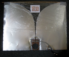
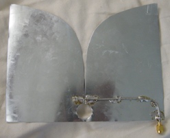
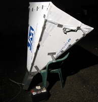

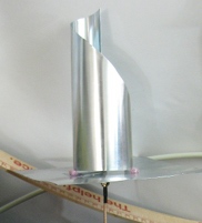
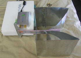
I think I like making antenna even more than using antenna. There's endless depth to it and it doesn't really require a ton of math or coding. It is like a free-form puzzle game: how do you redirect the largest volume of electromagnetic fields with the smallest volume structure over the largest range of wave sizes. For antenna sizes larger than 1 wavelength the answer is almost always one or more focusing reflector surfaces. But when it is under one wavelength things get interesting.
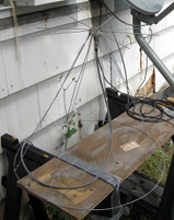
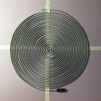
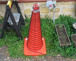
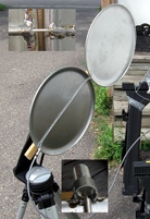
A broadband antenna is one that has at least -15 dB return loss continuously over a range at least ~40% (1.4:1) of the center frequency. Often technical papers relax this to -10 dB return loss (~2:1 SWR) or even -5 dB return loss (~3:1). They're very convient for radio monitoring but come with their own set of challenges in both implementation and performance. The above show some of the broadband antenna I've made.
By design broadband antenna pick up everything. This includes powerful radio frequency interference (RFI) that overloads your frontend amplifier. This can be in the form of quieting due to amplifier compression and/or as images at harmonics of the powerful signal due to the mixer filters not attenuating enough. Because a broadband antenna is pretty useless with a bandpass generally you need to use bandstop filters with high upper passbands to mitigate this problem. So sometimes your filter determines usable bandwidth regardless of antenna impedance bandwidth.
To avoid using a restrictive filter you can use an antenna that has high gain/directionality. But then the pattern bandwidth needs to be even larger than the impedance bandwidth otherwise the antenna will have sidebands outside of the design range that pick up strong interferers. The quality of the pattern bandwidth often depends on balancing contributions from both electric *and* magnetic dipoles in the same design. In horns this is called a hybrid mode feed. In the K-antenna TEM horn a literal magnetic loop is embedded in the structure to mix with horn surface arms.
A lot of wideband/broadband antenna and their feed structures have weird impedances that require some means of smoothly changing the line impedance to prevent reflections when connecting to common coaxial cable and receivers. In many cases these impedance transformers only work for a reduced, and sometimes fairly narrow, frequency range (ie, 1/4 wave long tapered impedance sections).
Tapered helical antennas tend to have an impedance of about 100 Ohm. But there's a trick to feeding it that can sometimes be generalized to other antenna types. By feeding both ends of the monofilar helix, one at the normal point and one at the tip, two 50 ohm feeds of different frequency and opposite circular polarization can be combined for a 50 ohm output. Multiple feed antenna types like the "eleven antenna" or spirals with more than two arms use multiple coaxial cables as well. But this just shifts the broadband requirement to the 180 hybrid mixer or balun used to combine them.
Usually your transmission line is an unbalanced line (ie, coaxial cable) but the antenna often balanced. In order to prevent currents on the shield of the coax from interacting with the antenna a balun is required. Often times these baluns only work over a fraction of the bandwidth stated for the antenna or feed itself. The infinite balun of a coaxial spiral or conical spiral is the only simple large bandwidth balun but it is specific to using coax as the antenna element(s) and the length leads to resistance loses. K-antenna and other TEM horns can use mechanically complex Klopfenstein (1/2 wavelength long) or "tulip" (1/4 wavelength long) tapers of the outer conductor in a coaxial cable to a parallel plate configuration. Other times exponential parallel plate to stripline transitions are used.
A lot of wide bandwidth antenna have the conductive elements that scale from the small to the large. Different parts of the antenna are used in reception of different frequencies. Usually the feed is near the small end and so the high frequency component of an RF impulse is received first by a small time. This smearing of the different frequency components out over time is called dispersion. Some antenna like planar/conical spirals, log periodic dipole arrays are particularly bad about this. They are not optimal for UWB pulse modes. Antenna that have bad dispersion generally have a variable phase center with respect to frequency and have to be moved if used as reflector feeds.
