Mesh networks require height. Height is expensive. What are some alternate ways to get height and what are their DIY enabling technologies?

2019-11-05 #1

Mesh networks between people are an alternative to the internet are hard. Height above terrain is everything in the VHF and up range if you're not in a giant city of skyscrapers or coastal town with giant mountains overlooking everything. It's just not possible to put together networks if there are many hills or valleys obstructing line of sight. The only reason cell networks work is that they buy space on towers, buildings, and the like high above the ground. That's too expensive for individuals or community groups. There are some non-traditional ways to get height and power up to that height, cheaply.

Surface wave transmission lines going up to antennas in trees

The first I've tried was making a light weight transmission line to connect a ground level transceiver with the antenna hanging up in a tree. RF power can be carried on a single thin bare (28awg) wire in much the same way that it travels inside a waveguide but inverted (TEM). This surface wave transmission line (SWTL) just requires a couple complex metal tapers making up horns at both ends. These can be 3D as in the designs from Glenn Elmore in QEX I implemented or 2D as shown in some of Glen Elmore's more recent youtube demostrations of high power (50w) tranmission at high effiencies. Though it's complex to make the 3D version like mine the 2D design made of metallized paper that Elmore demostrates could easily be DIY'd. Rain, snow, and ice are problems but sometimes working is better than not at all. Loss is low and they aren't an eyesore to the neighbors. For higher frequency band (ie, 2.4 GHz and up the launchers can be very small. The 2 launchers I made shown below are designed for a ~400 MHz lower cut-off and so quite large.

Magnetrons as reflection amplifiers

The second, one I'm only exploring in theory right now, is using very high power by operation of cheap oven magnetrons as reflection amplifiers. When an external signal up to ~30 dB below the cavity's operating level is introduced the cavity behaves like a diode with negative resistance and will lock on to the introduced signal and amplify it significantly. Normally over magnetrons are fairly noisy outside of the carrier because of electrons that make it more than one loop around the cavity. This can be stopped by making the magnetic field asymmetrical vertically by adding a handful of extra neodynium magnets to bias one of the poles. Additional reduction in noise can can be had by minimizing cathode heating current if not turning it off entirely. Magnetrons in ovens operate at a power level well above what they can sustain in steady state. To reduce the power level to something that can be dissipated the input capacitor on the voltage doubler needs to be reduced to one about 1/50th of it's capacity of a similar or higher voltage rating. This results in output power levels in the 10s of watts with very low noise and a decent modulation depth.

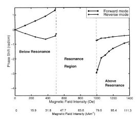
Magnetrons' innate frequency of oscillation can be effected by many things during operation. Increased anode current "pushes up" the frequency at about 0.1 MHz/mA while the frequency is "pulled down" the lower the impedance of the output. By using a slightly shorter than 1/4 wavelength monopole the frequency can be shifted some tens of MHz down to well within the safe amateur radio operating band. External coils wound around the poles of the magnetron can be used to change the magnetic field intensity and so decrease the amount of electrons that make it from the cathode to anode at a given voltage decreasing the power.

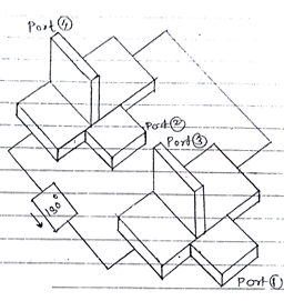
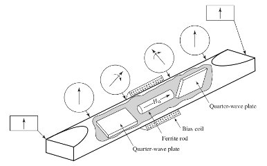
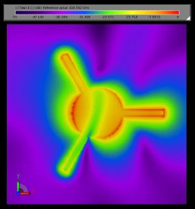
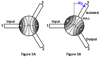
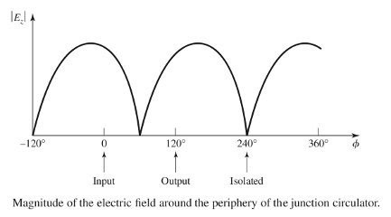
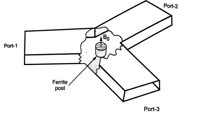
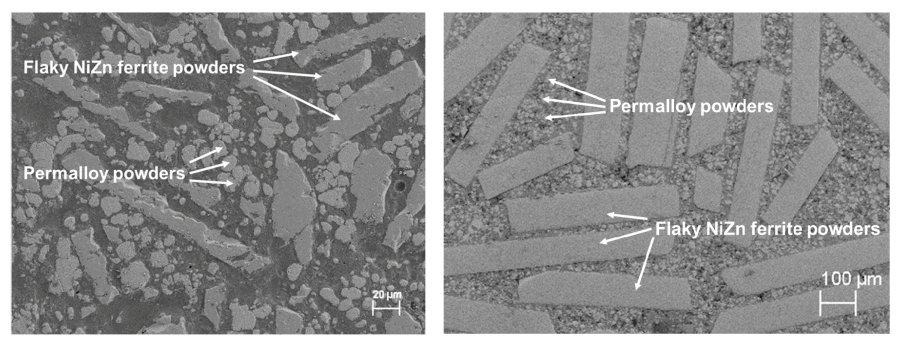
The one problem with magnetrons as reflection amplifiers is that the magnetron is only one part of the amplifier. The other is the circulator. Circulators are not cheap. And circulators cannot be home made because of the sintering and pressing requirements even if the chemistry of nickel ferrites is easy to do. So they must be bought ($50-100 for 50w). Ferrimagnetic resonance stripline circulators tend to be the cheapest at these powers.

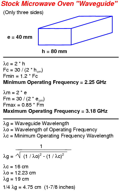
In terms of practical assembly, the microwave is left mostly assembled. The output of the TE_10 waveguide is closed off with a copper plate and another magnetron cap "probe" antenna is put into the sealed waveguide ~1/4 wave away from the newly shorted end of the waveguide. The output of the monopole is connected directly to the circulator tab despite the weird impedance probably presented. The input from the signal to be transmitted and the antenna (or SWTL launcher) are on the other two pins of the circulator.

Combining it all together

10-20w of power on 2.4 GHz that's transmitted as 5-10w from the antenna at the top end of a surface wave transmission line lofted in a tree at 70ft would enable whole town and true community mesh networks. The injection locking effect only works over a ~5 MHz range though. Any modulation scheme has to stay within those bounds but things like amplitude shift keying are bad choices because of the frequency pushing effect. The best modulations are FSK or MSK but BPSK does work at a slightly higher error rate. A handful of megabits per second is possible.


opml to html, or, I know you're not supposed to use regexes but fuck it

2019-11-06-1 #1

I tried to do it the right way. I tried all the xml manipulation libraries. But they all failed. Or I failed them. Either way it was just faster and far easier to do it with regex than attempt to learn some new xml module. So here is the dirty result that makes /feeds.html on my site from the opml that QuiteRSS spits out.

#!/usr/bin/perl -w
# Usage: regexopmltohtml.pl foo.opml > bar.html
use strict;
my $opmlfiletoparse = shift;
open( THEFILE, "<$opmlfiletoparse") or die "Can't open file $opmlfiletoparse $!";
while(<THEFILE>) {
	if ( m{<outline text=\"(.+)\">\n}sg) {
		my $name = $1;
		print qq[<hr />];
		print qq[<h3>$name</h3>];
	} elsif ( m{<outline text=\"(.+)\" type=\".+?\" htmlUrl=\"(.+)?\" xmlUrl=\"(.+)\"/>}sg) {
		#print "1: $1, 2: $2, 3: $3\n" if $1;
		my($name,$htmlurl,$xmlurl) = ($1,$2,$3);
		print qq[<p>];
		print qq[<a href="$xmlurl"><img src="/rss.png" border="0" /></a>\n];
		print qq[<a href="$htmlurl">$name</a></p>];
	}	
}

Microwave ferrites: can they be made DIY? No. But I learned I was asking the wrong question.

2019-11-07-1 #1

Most of the cost of a magnetron reflection amplifier is in the circulator. High power circulators are weird and expensive but you can't build a reflection amplifier without them. Even just ordering special microwave ferrite material is almost as expensive as the finished circulator (if they'll sell to you at all). So naturally I wondered if I could make a ferrite disk, and from it a circulator, cheaply at home. Nickle ferrites are the most applicable because they can be worked in air. The two feasible options seem to be water chemistry nanoparticles, pressing, then sintering or low temp curing pourable magnetic composites made of expensive monomers, permalloy powder, and powdered oriented-strand 3M magnetic sheet.

But in the process I learned there's nothing special about garnet or other microwave ferrites. They just have a small resonance line width leading to low loss. The same non-reciprocal ferrimagnetic resonance happens even mass produced cheap iron ferrite rods and might work for an extremely lossy demo. Or at at high power but low duty cycle when you don't care about energy efficiency...like if you had a injection locked magnetron and bursty power to spare.

tldr: Home manufacture of microwave ferrites might be cheaply feasible *but* reuse of common cheap ferrites as lossy circulator elements certainly is and it's immediately accessible.


Circulator theory

A circulator uses some non-reciprocal material that allow transmissions lines to work differently depending on which direction the RF is traveling. In electromagnetics non-reciprocity is almost exclusively obtained through Zeeman splitting in (ferrite) ferromagnetic materials using a static magnetic bias that splits degenerate atomic states with opposite spin. These opposite spins have slightly different energy and so different frequency. In the plot on the right below this frequency difference is represent as advance or retreat of phase.

For circulators made of ferrites there are two ways main ways to use this. 1, magic-tee waveguides connected by two paths where one path is loaded with ferrite that causes faraday rotation of polarization (equiv to 180 deg phase shift) causing two-path interference in one direction but not the other (youtube link).

And 2, Y-junction transmission lines with ferrite resonators disks that have standing waves with nulls that can be rotated by an external magnetic field to so that the voltages at different angles around the perimeter of the resonator can be maximized and minimized.


The standing wave is actually two counter-rotating wave patterns. When there's no external magnetic field they rotate at the same frequency. When an external magnetic field is introduced the frequency of one is shifted and the resulting interference pattern is rotated. Despite the complexity of the physics in terms of mechanical construction a round ferrite waveguide based Y-junction circulator is by far the easiest design to make. And it's the easiest with which to connect a low power magnetron. The most straightfoward approach is the traditional 80*40mm TE_01 waveguide dimensions for the three arms.

Ferrite chemistry and mechanical production

The actual ferrimagnetic resonance is a frequency where the circulators *don't* work and they have to be designed with the target frequency either above the resonance in frequency or below it. Above or below resonance operation, depending on if the precession frequency is higher or lower than the RF frequency. The size of the the resonance in frequency span is called the line width and it determines the loss of the material. Expensive, densely pressed garnet ferrites have very low line widths and work over a broader range at lower loss.

But this doesn't neccessarily mean that homemade nickel ferrite would have no use in a circulator. It'd only be lossy. So what I'm thinking about here is using simple water based chemistry with ferrite chloride and nickel chloride chelated to co-precipitate a nickle ferrite and attempt to manufacture the a homemade waveguide y-junction circulator.

Nickel Ferrites may be the least complicated ferrite from the processing point of view. The nickel remains essentially in the Ni++ state so that air is almost always used as the firing atmosphere.

For co-precipitated "ready" powders, like the above example, sintering temperatures can be as low as 900 C. That's plausible to do with a cheap induction heater like I have. The press could probably be a simple hydraulic press. Papers quote pressures around 100 MPa, so for a 3cm diameter disk and a 2 metric ton press thats: (2 tonne)â‹…(9.8m/s^2)â‹…10/(piâ‹…1.5cm^2) = ~200 MPa. Plenty of margin. A $20 hydraulic bottle jack for trucks does about 6 ton. Though I imagine the limiting factor would be the threaded rod and nuts used to make the press frame. But it'd probably still have voids without proper compaction machines and the effective line width would be higher. So much higher that an improperly home-pressed nickle ferrite would probably be no less lossy than an industrial pressed iron ferrite availably commonly for cheap prices.

Pourable ferrite composites with no press and low temperature curing

But even a cheap press is an expense and a somewhat bulky and dangerous thing. And sintering at 900 C is hard in implementation. There are some papers about pourable low-temperature cured pourable magnetic composites. But most of these have terrible specs. Except one 2019 paper, A (Permalloy + NiZn Ferrite) Moldable Magnetic Composite for Heterogeneous Integration of Power Electronics that has both decent performance *and* it's easily manufactured DIY. It's a mix of expensive (but feasible) permalloy magnetic powder with NiZn ferrite from crushed up 3M Flux Field Directional sheet and expensive and infeasible to get trimethylolpropane triacrylate (TMPTA) monomer. If a source of that last one that sells to individuals could be found it might just work.


Linux software stack future shock

2019-11-30-1 #1

In the old days I'd build a new computer because the old one's hardware wasn't fast enough to run new software. Now hardware from 2013 is plenty capable of running whatever you throw at it but if the software stack is a similar age don't expect to be able to run any new software or even decode video media. The rate of change in technological progress on the software side has only continued to increase, unlike hardware.

Because of rapid development of the previously somewhat bi-decadal-stable programming libraries (and codecs) everyone uses (C++'s C++11, C++14, C++17, C++20, changes to glibc adding new functionality, etc) it's almost to the point where you can't compile something written today on a software stack more than 5 years old. The proliferation of all the containerized solutions (docker, flatpak, snap, appimage, etc) is the immune response to this inflammation but it just makes it worse. Progress is great but the rapidity of obsolescence is getting intolerable.

Yeah, I could throw away my old software version workflows and update to lastest $OS but I think it's a lot easier to just build a new machine to add to the span.


Photos of unpleasant alleys at night in winter

2019-11-30-1 #2