I've done open loop bandpass filters before but my prior design had no way to tune anything. It was just one band per design.
This is my attempt to implement a tunable radio frequency bandpass filter based off a paper I read. It uses planar PCB resonators that are tuned by a "digitally tunable capacitor" IC controlled by an esp8266 microcontroller.
I'm basically implementing the paper, "A UHF Third Order 5-bit Digital Tunable Bandpass Filter Based on Mixed Coupled Open Ring Resonators" by Ming-Ye Fu, Qian-Yin Xiang, Dan Zhang, Deng-Yao Tian, and Quan-Yuan Feng. But I translated the intent of the design from 0.8mm expensive (Er 2.65) PCB material to cheap 1.6mm thick FR4 PCB (Er 4.4) and I'm rolling my own microcontroller setup since theirs is not described.
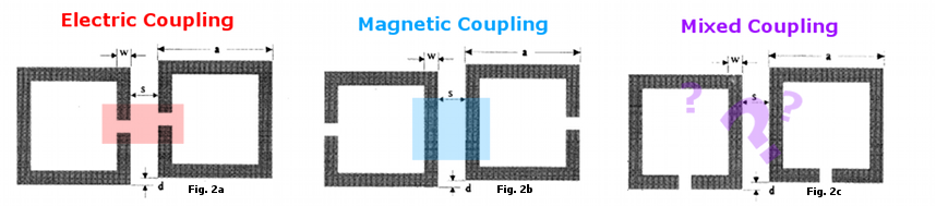
In open loop resonators very close to each other the type of coupling, either electric of magnetic, is a function of the location on the loop(s). At resonance the maximum electrical field density is across the gap and the maximum magnetic field density at the opposite side. So for magnetic coupling they are put "back" to "back" and for electric "face" to "face". By turning them so neither the max electric nor max magnetic field densities are close to the other the contribution of electric and magnetic coupling is about the same. This is called mixed coupling.
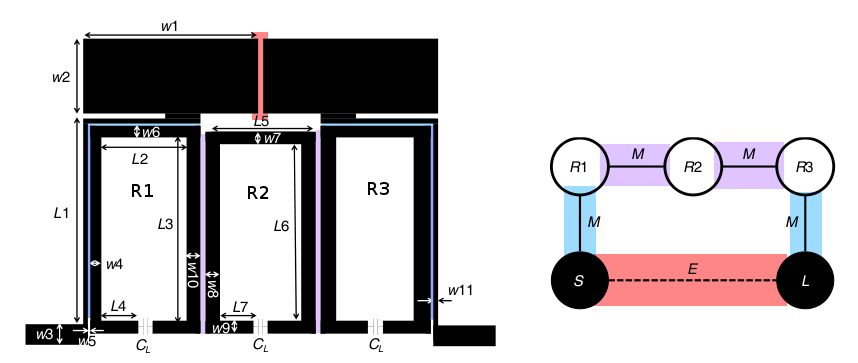
In this particular design RF energy initially couples in from the source between the skinny, inductive, microstrip trace that go up and traces the perimeter of the first open loop resonator. The microstrip goes along one side getting "mixed" coupling but then continues all across the top where the peak magnetic field density is. This magnetic coupling dominates the weaker mixed coupling and it is mostly magnetic from source to resonator 1. This is also how energy gets out from resonator 3 to the load, L.
The middle open loop resonator is aligned for mixed coupling with it's neighbors but also slightly displaced down from the other two to fine tune this balance.
The thin trace going up the outside and the capacitor rectangles up top are designed to resonate at a bit above the passband frequency and cause a 90 deg phase shift that leads to destructive interference when it's signal is recombined with the open loop path at the load port.
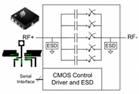
The tunability comes from using some really neat Peregrine Semiconductor IC called the PE64904; a "Digitally Tunable Capacitor" that works from 100-3000 MHz and spans 0.6 to 4.6 pF. This IC is put in the open end of the open ring resonators to tune them. It is controlled over the 3-wire SPI protocol which necessitates a microcontroller of some sort. I've chosen to use the cheap esp8266 series esp12e boards (~$5) because they come with wifi and I already have experience with them.
The commands it takes are very simple. You pull the chip select (CS) line low then send a message containing a hex number from 0 to 31 and return the CS high.
You may be thinking, "Why not use varactors instead? Then you don't need a computer you just need a variable voltage. It's much simpler." And it is in an absolute way. But the complexity of using a digital computer to control things is something I'm used to while designing a variable 0-30 voltage source that's precise and repeatable is not. And most importantly: the guys in the paper did it this way.
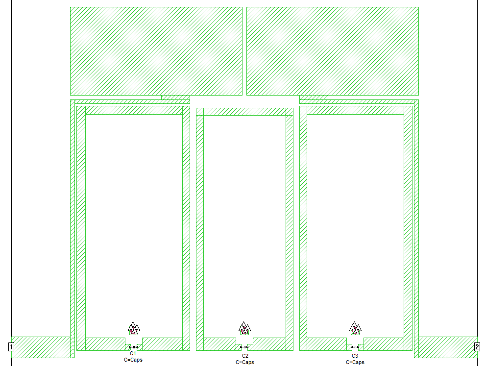
Below is the design as I implemented it on 1.6mm 4.4 dielectric FR4. For scale, the input port microstrip is 2.5mm wide (~55 Ohm). I compromised on a grid size of 0.125 mm and this led to a sim time of about 5 minutes (i5 3750K processor). The granularity of the grid to get this decent iteration time made directly copying dimensions infeasible even if they hadn't used 0.8 mm 2.65 dielectric F4B-2 substrate.
I ended up spending a bit of time using an online microstrip electrical length/phase calculator to translate the intent of the shapes to my different PCB material. And then a bit of fiddling back and forth with values when it didn't quite work.
The little square pad with a via in it is for the PE64904 footpad ground. The two 0.75mm bits at the throat of the open loop are also to conform to the IC pads. I also tried adding the other IC footprint traces but the distance between them was very small and when I tried approximations with just one it didn't have much effect.
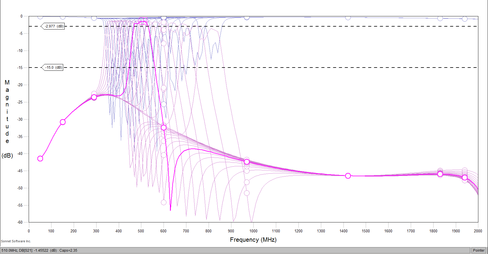
I set all the capacitors to the same variable, Caps, then did a parameter sweep of Caps from 0.6 to 4.6 mm at step size of 0.125 pF which is 32 steps and matches the PE64904 step size of 0.13 pF. Every other step is shown in the scattering parameters plot (0.25 pF step, 16 total).
The results matched the response reported in the paper pretty darn well.
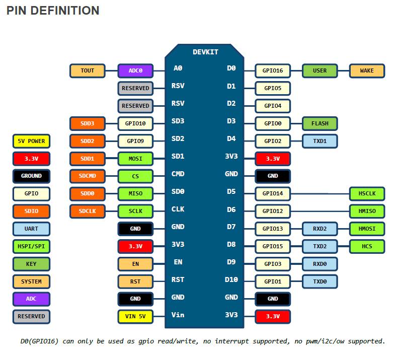
This lua code connects to to a hard coded wifi ssid then once it has an IP it connects to a TCP server running on a hardcoded IP and port. From there it waits for text instructions. On receiving anything in the form of a number from 0 to 31 it converts it to hex and sends it out the configured HSPI port to the digitally tunable capacitor.
Normally GPIO15 (pin D8) is used as a SPI 'Chip Select' line. But this requires adding external resistors in order to not trigger some boot issue. Additionally people on the forums have reported HSPI CS not working with NodeMCU. So since the PE64904 only requires 3 wires I instead disable the HSPI CS (GPIO15/D8) and the HSPI MOSI (GPIO13/D7) by setting their mode back to normal GPIO. Then I use the HSPI MOSI pin as a GPIO and manually pull it low as a chip select command before spi.send() then manually set it high after.
For a server on the computer it connects to I use use netcat like,
nc -l 6005
and then type, say, 15 and hit enter. If it works it responds "ok".
15
ok
-- esp8266 mediated wifi:telnet control of PE64904 SPI based digitally tuned capacitor.

-- Config				esp12e		PE64904
-- local CLK = 5           	 --> GPIO14 D5 | MISO, PIN 7 (SDA)
-- local MISO = 6            	 --> GPIO12 D6 | SCL,  PIN 5 (SCL)
local CS = 7              	 --> GPIO13 D7 | SEN,  PIN 6 (SEN)
local duration = 3000     --> 3 seconds
local i = 0
local result = 0

-- Manual CS Pin (instead of HSPI CS)
gpio.mode(CS, gpio.OUTPUT)
gpio.write(CS, gpio.HIGH)

-- Need to disable HSPI CS D8/GPIO15 from being toggled.
-- Set pull-up to prevent potential issues.
-- ref: https://nodemcu.readthedocs.io/en/master/en/modules/spi/#spisetup
gpio.mode(8, gpio.INPUT, gpio.PULLUP)

-- print ap list, wifi.sta.getap(listap)
function listap(t)
      for k,v in pairs(t) do
        print(k.." : "..v)
      end
end

function string.fromhex(str)
	return (str:gsub('..', function (cc)
		return string.char(tonumber(cc, 16))
	end))
end
function string.tohex(str)
	return (str:gsub('.', function (c)
		return string.format('%02X', string.byte(c))
	end))
end

-- Connect to wifi
print(wifi.sta.getip())
wifi.setmode(wifi.STATION)
wifi.sta.config("wholikeslinux","Xplr24242")
print(wifi.sta.getip())

-- Phone home to see if it's working
-- conn=net.createConnection(net.TCP, false)
-- conn:on("receive", function(conn, pl) print(pl) end)
-- conn:connect(80,"superkuh.com")
-- conn:send("GET /esp8266 HTTP/1.1\r\nHost: www.superkuh.com\r\n"
--     .."Connection: keep-alive\r\nAccept: */*\r\n\r\n")

-- Connect to control server
local flagClientTcpConnected=false;
print("Start TCP Client");
tmr.alarm(3, 5000, 1, function()
	if flagClientTcpConnected==false then
		print("Trying to connect to server");
		local conn=net.createConnection(net.TCP, false)
		conn:connect(6005,"192.168.1.125");
		conn:on("connection",function(c)
			print("TCPClient:connected to server");
			flagClientTcpConnected = true;
		end)
		conn:on("disconnection",function(c)
			flagClientTcpConnected = false;
			conn=nil;
			collectgarbage();
        	end)
		conn:on("receive", function(conn, m)
			print("TCPClient:"..m);
			for i = 0,31 do
				if string==i then
					hexval = i.tohex()
					gpio.write(CS, gpio.LOW)      -->Activate the SPI chip
              				tmr.delay(1)                  -->1us Delay
					wrote = spi.send(1,hexval)    -->Write hex value
					gpio.write(CS,gpio.HIGH)      -->De-activate the SPI chip
					print("Started SPI DTC Control");
					conn:send("ok\r\n");
					tmr.delay(100)
				end
			end
		end)
	end
end)