Home: Planar PCB Radio Filters
It's a bandpass filter that uses a coaxial cavity made of a post and a ring of vias shorted at one end (bottom) and loaded with lumped discrete capacitors at the other (top). It's really small relative to wavelength for decent performance (-20 dB return loss, -0.5 dB insertion loss).
I'm basing some of it off the paper, "A Multi-Evanescent-Mode Coaxial Cavity Resonator" by Jin-Song Zhan, Shi-Wei Dong, Li-Ming Gong, Shao-Feng Dong, Xiao-Long Chen, and Jia-Li Wang. This paper has no photos and only confusing models of the physical layout. I also used a different thickness PCB with different dielectric constant. So I guessed at and changed things like transmission line widths and capacitor placement.
Abstract-This paper presents a novel miniaturized multi-evanescent-mode resonator. The resonator
is achieved with a coaxial cavity. This coaxial cavity essentially has a direct short connection at one
end and is connected with several lumped capacitances at the other end. The key technology of the
resonator is the usage of multiple evanescent-modes of TM (transverse magnetic wave) modes. Due to
the combined effects of the evanescent mode and multiple modes, the size of the resonator is greatly
reduced. In this paper, the theory of resonator is discussed in detail. To verify the correctness of
operation, the resonator is used in experimental measurements conducted to realize a third-order band-
pass filter based on SIW (substrate-integrated waveguide) technology. The measured results are found
to agree with the theoretical values.
[comment on this post] Append "/@say/your message here" to the URL in the location bar and hit enter.
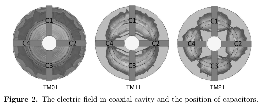
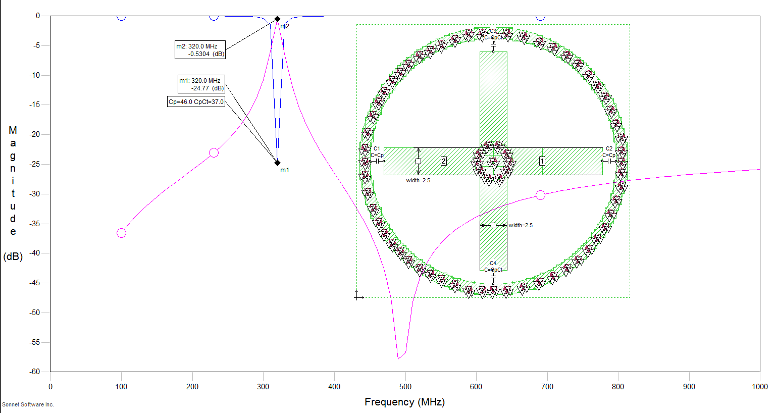
This is a peculiar design. A dielectric filled cavity is made with plated vias in a circuit board. In the center of this, coaxially, is a post made of vias and a top metallization disc. This post/disc is connected to the via wall cavity ground by 4 microstrip transmission line arms that terminate in capacitors. The capacitor placement is arranged so that they are in the areas of max electrical field for the 3 evenascent modes of the design.
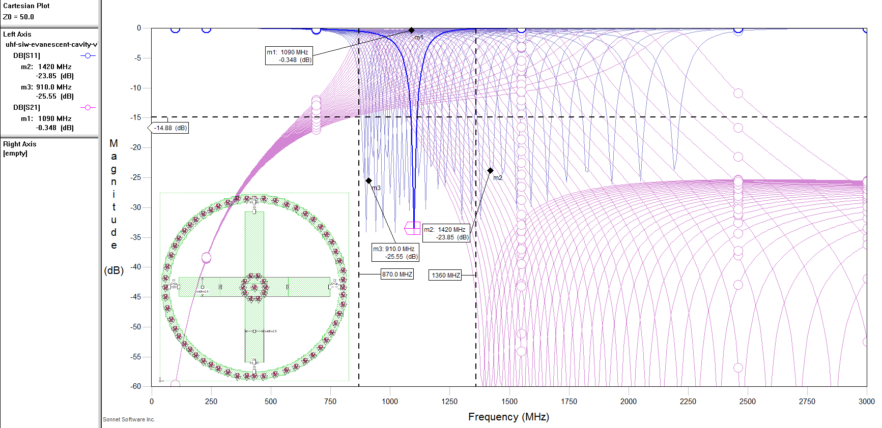
The high quality inductance of the microstrip lines and a high-Q SMD capacitor make for decent Q resonators. The difference in capacitance between the vertical and horizontal arms defines the bandwidth of the filter. The two vertical lines are always terminated with slightly less capacitance than the two horizontal ones (where the feeds tap). Generally that's about 5 pF difference, but altering the relative values of Cp (horizontal) and Cp-Ct (vertical) gives some freedom in shifting peaks and optimizing S11.
The feeds are SMA probes up through the bottom of the cavity and they terminate 4.5 mm away from the center of the post. This is the trickiest thing, I guess. Will 4.8 mm of probe length change the results with it's series inductance? Only testing for real will tell because I don't know how to figure it out. In Sonnet you can have internal ports but they have to be at the edge of two conductors.
In order to work with low loss the cavity had to be about 5mm tall (unlike the paper's suggested use of 2.5 mm). So that means 3x 1.6mm boards in a stack. One bottom board with full ground and a via/metal-ring on top. One middle board with no ground and a via/metal-ring on bottom and top. One top board with no ground but the a via/metal-ring on bottom with the resonator top disc, microstrip lines, cap pads, and via ring. A 5mm box ceiling is required but the board doesn't have to be suspended.
0.027 wavelength * 0.027 wavelength * 0.005 wavelength
It probably won't work.
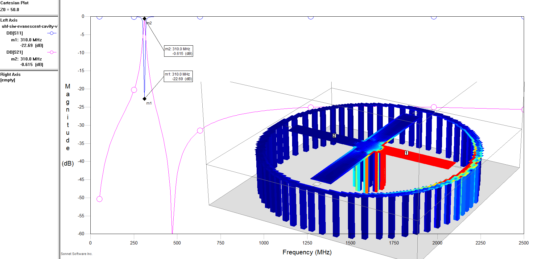
While playing around down in low UHF (~300 MHz Cp=41pF) I noticed that this filter functions just as well, or better, at higher frequencies. The only thing that needs to be changed is decreasing the lumped capacitance to couple to the reduced inductive reactance of the transverse magnetic (TM) coaxial evanescent modes. So the same filter could be for many bands just by adding an extra cap or removing one. Though at higher levels (@low freq) the tuning range would be swamped by the increased base capacitance added. So it's only widely tunable at higher frequencies.
At the very low end near 0.6 pF the capacitance step size of the digital caps, ~0.125 pF, shifts the resonant frequency so much that there are gaps between pass bands. So the tuning can only extend up so far with full coverage.
I scaled the gap between the lines and the top ring to the size the Psemi DTC requires for it's shunt-mode configuration. But I'm not adding in control lines yet because, frankly, I don't know how or where.