Last updated: 2013-01-13
Dodgy plans to make Archimedean spiral antenna for RTLSDR (software defined radio receiver)
Resources Utilized
[antenna-theory.com: Spiral Antennas, video, infinite balun description], misc papers on spiral antenna, including Dyson's 1959, Modern Antenna Design_ Thomas A Milligan_ 2005 p.521-543, Antenna Engineering Handbook_ John Volakis_ 2007 Ch. 13-1 to 13-34 Ch. 13-55 to 13-64, Foundations of Antenna Theory and Techniques_ Vincent Fusco_ 2005 p.212, Analysis of Archimedean Spiral Antenna
[comment on this post] Append "/@say/your message here" to the URL in the location bar and hit enter.
An Archimedean spiral made of two equal lengths of coaxial cable seems to be the easiest circularly polarized antenna to make that'll cover a broad range of the rtlsdr dongles' E4000 tuners.
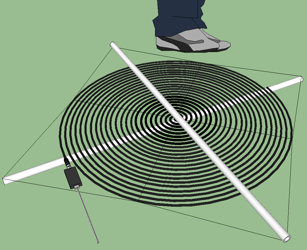
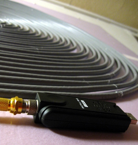
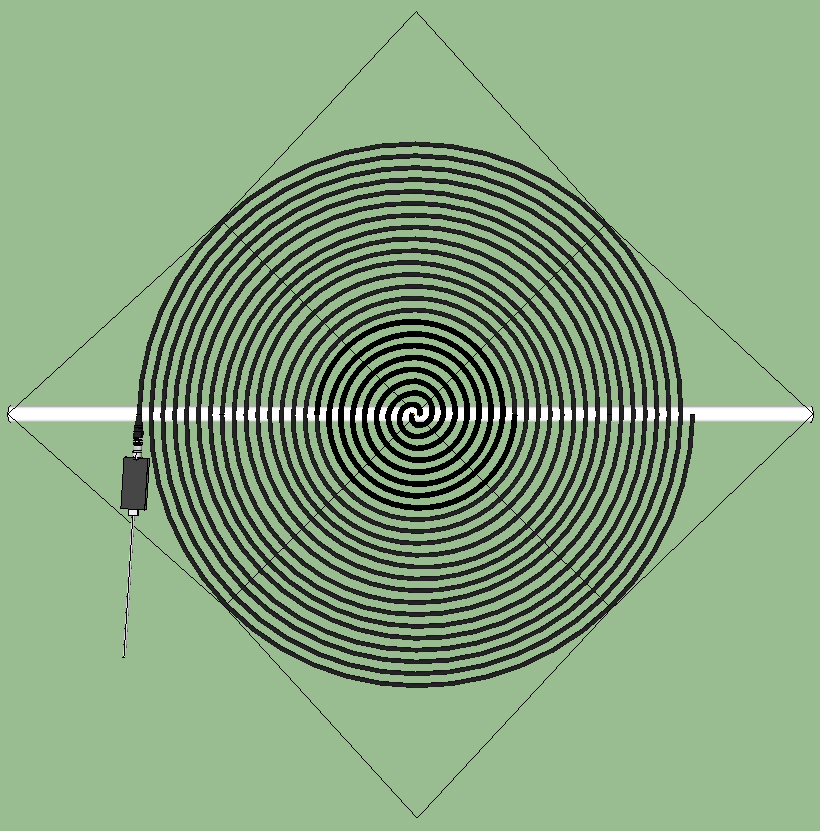
The actual build
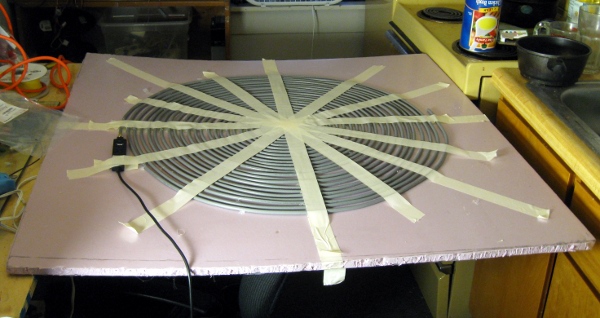
Assembly on the stacked PVC was annoyingly hard so I made it on plastic foam board first. I am taking data now and I am surprised by it's sensitivity down in the <100 Mhz range. I haven't watched long enough to find problems and on some higher frequencies it's 2-4dB less power than using a band appropriate quarter wave antenna. A lot of the variation could be from the directionality of the spiral antenna; I have it standing on edge perpendicular to the ground with the two lobes pointing north-south with the nulls towards the nearest metropolitan area.
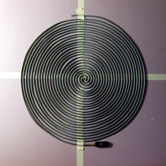
I made the guide by laying down two pieces of tape on 1/4" insulation foam board and marking it with sharpie. I started winding the first spiral arm in the middle (at the feed) and used tape to temporarily reinforce the shape while doing the innermost bend. The innermost bend had to be pre-shaped by bending the RG6 coax with pliars. I think I avoided kinking the dielectric. After the first few winds just tacking in place with hot glue worked. Just don't take it out into the sun without adding permanent fixation in the form of silicone glues or PVC and zip ties. I had the low temperature hot glue soften and detach requiring 30 minutes of repair work.
The inner feedpoint connection between the center conductor of the feed arm and the outer conductor of the other was made with regular and special aluminum silver solders after the two arms had been hot glued down to the board using a regular soldering iron. The rtlsdr dongle I'm using is hooked up with a 10m long USB active repeater extension cable and F crimp connectors.
I was able to decode WBFM in stereo with RDS decoding at 2.048MS/s so I don't think it's dropping many samples. For a choke I wound the usb cable ~10 times around a microwave oven transformer.
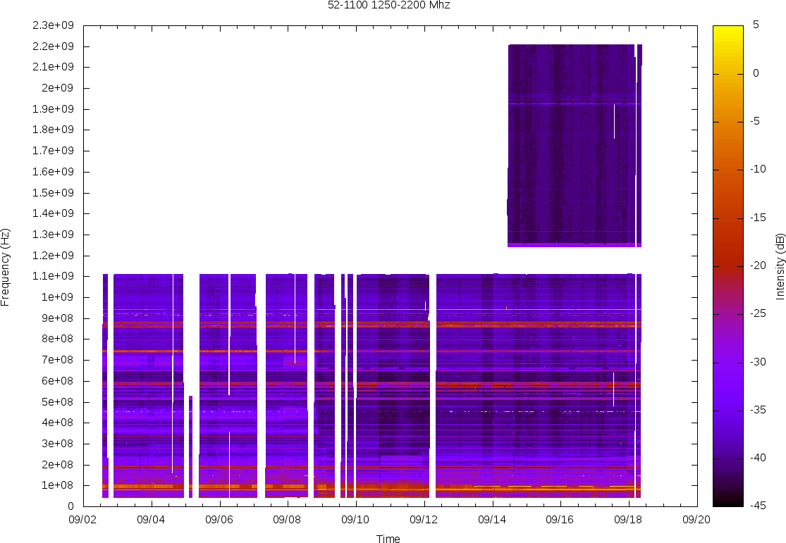
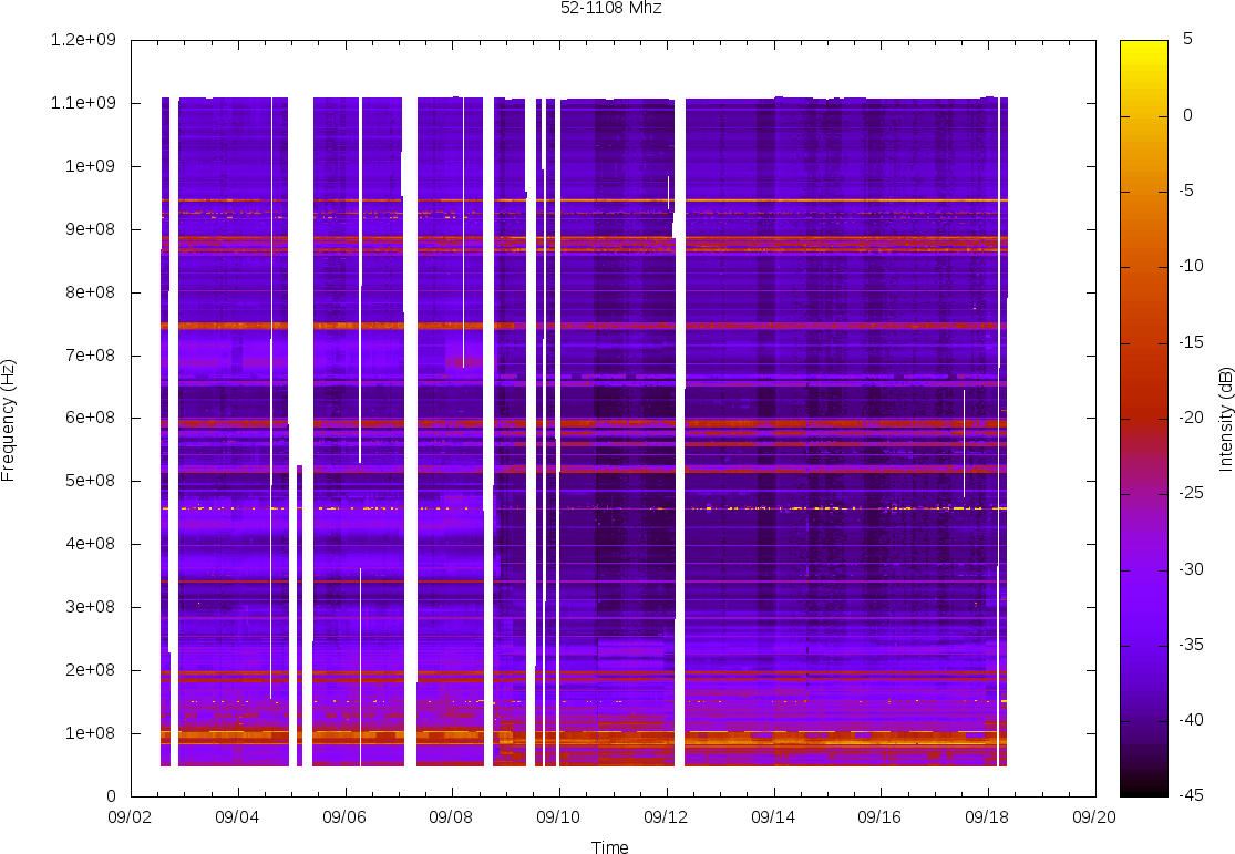
See the live data at my 52-2200Mhz radio scanner page. Her's an alternate single plot of 52-1108 Mhz. The antenna is inside an apartment with an electrical system so noisy the wall sockets literally make barely audible buzzing and clicking sound. I'm hoping to put it on a sun tracking mount outside soon.
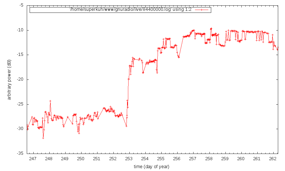
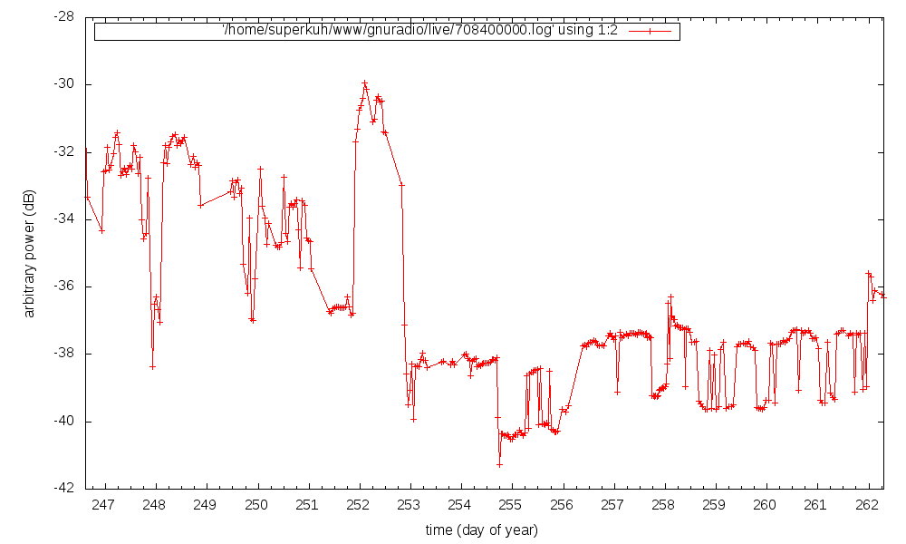
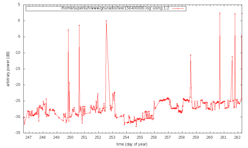
After a week of data I have to admit some negative differences in some frequency ranges despite much improved performance for the low frequency end (ex:84Mhz). The spiral antenna usage starts just before day 253 (Sept 11th) for reference. As compared to the set of 3 quarter-wave antenna used before drops of up to ~8 dB (relatively rare, ex: 709Mhz) but more typically 2 to 3 dB (more common and tens of Mhz wide, 156Mhz) occur. But those verticals were next to a desk with a noisy LCD monitor where the large spiral cannot fit when I point the spiral at the monitors I get similar data. I don't know anything about absolute performance of this antenna yet.
In addition to the lower RFI of the different placement I think some lower signal is because of the variable spacing between the two coaxial cables. It's tough to wind it just right. That might effect the distributed capacitance and inductance which might result in reflections from the impedance changes. So frequencies with their action regions near the gap spacing variation might have low sensitivity. I notice that when I reposition an out of place arm some frequencies will improve... but others degrade. I'm doing a bit of trial and error to tune it for even performance. Or it could be the effects of a not-perfectly-complementary structure where the gap spacing does not equal the conductor width that I'll just have to live with. Some sort of standardized spacer would help. I've been moving and reorienting the antenna in and outdoors since day 253 as well, so some of the variability is from that.
Qualitatively, I've been able to do wideband FM stereo decoding with RDS, gr-air-modes ADB-S decoding, 6m ssb, fm police/emergency chatter, pager pocsag, and LTE Cell scan stuff as easily as I did with 1/4 wave verticals before.
Pre-build design and theory
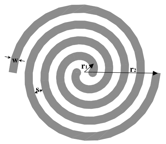
150-3000(?)Mhz, 11.5 turns, (0.5cm r_1 / 0.5 cm w) = 1, (s/w) = 2, SketchUp 7 model (6.2MB)

r = r_1 + aφ

r_1 = 0.005m, 1/2 distance between spiral elements
r_2 = 0.365m, from spiral center to outermost spiral tip
a = 0.03m, growth rate, distance increased from origin in one full turn
φ = angle, one turn: 2π or 360 degrees, to one "a"
w = 0.005m (5mm), arm width of spiral conductor
s = 0.01m (10mm), spacing between each turn
N = 11.5, number of turns

Low frequency limit guesses:

	the speed of light / (2 * pi * 0.365m) = 130.7 Mhz

	circumference of circle at widest point should be 1.25λ of lowest frequency
	(2*pi*0.365m)/1.25 = 1.834m, c/1.834m = 163.5 Mhz

High frequency limit guesses:

	the speed of light / (4 * r_1 )
	= c / (4 * 0.005 m) = 15 Ghz (max for 1/4th wave across 2*r_1, not realistic?)

	Over-mode noise, <2.6dB ripple when 80% of 0.254λ, 0.20λ > inner diameter
	150Mhz 	0.2*1.998m  ~= 40cm
	1.5Ghz 	0.2*19.98cm ~= 4cm
	2Ghz	0.2*15cm    ~= 3cm
	3Ghz	0.2*x10cm   ~= 2cm
	6Ghz	0.2*5cm	    ~= **1cm** (upper limit for 2*r_1, 2*0.5cm, 1cm)

Polarization: RHC polarization on one side and LHC polarization when flipped over.
Length of coax in one spiral arm = ~12.83m
I am not very sure at what the upper frequency limit will be. I think it will be well above the 2.2Ghz limit of the E4000 tuner so I don't care too much.
Theory Notes
To be clear, most of these diagrams and excerpts are from the the books and papers I read. I did not produce them. The reference used is usually cited below the diagram or quote.
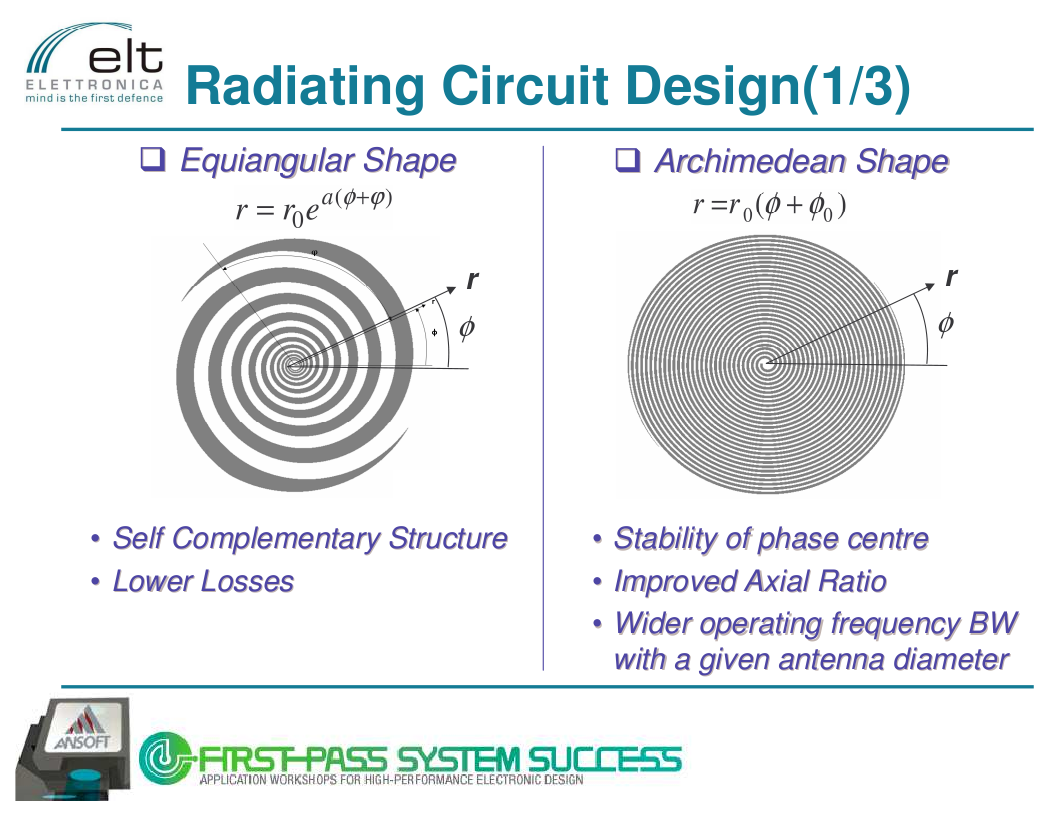
Self-complementary structures
"We can make a structure with logarithmically scaled radiating parts along a transmission line and still not achieve a successful broadband antenna. The parts must couple electromagnetically, not just through the connection of the feeder. We place dipoles of the log-periodic dipole antenna close together to produce the coupling needed for rapid attenuation. Similarly, we closely space the turns of a spiral so that the arms couple and there is sufficient length in the active region along which to radiate. Usually, we can account for the rapid attenuation of currents through loss of power in radiation by considering a single mode."
-- Modern Antenna Design by Thomas A Milligan, 2005, p.541
Arm width versus inner radius
Archimedean spirals aren't fully self similar since they are not scale invariant but apparently they behave a lot like equiangular spiral antenna. To be self-complementary the area of metal conductor and air (dielectric) should be equal; able to be switched with no change in the antenna's structure. For an archimedean spiral this means the width of the spiral arm, w, should be the width of the gap between arms, s. Additionally, the inner radius, r_1, should be equal to both. If it is not, the impedance varies greatly by frequency. In my design r_1 = w, but s/w = 2. I think it is close enough that it'll act self-complementary to a degree.
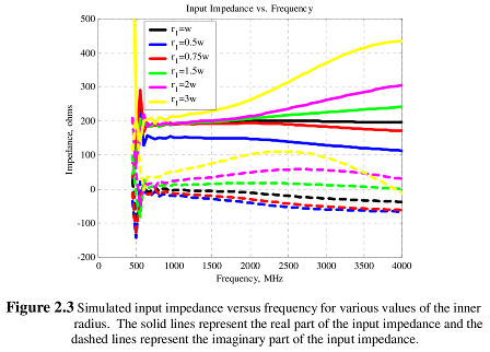
"When the inner radius is less than the arm width the real part of the input impedance is less than the desired 188 ohms, and when the inner radius is greater than the arm width the real part of the input impedance is greater than expected. Also, when the inner radius is not equal to the arm width, both the real and imaginary parts of the input impedance vary greatly with frequency."
-- Analysis of Archimedean Spiral Antenna, p.4
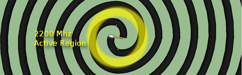
Active regions
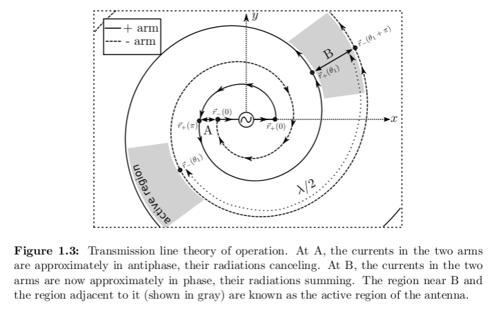
"A balanced line feeds the spiral from the center. The radiations from the nearly equal and opposite currents at the feed point cancel in the far field. The growing spiral arms separate the currents. When the perimeter of the turn approaches one wavelength, the out-of-phase currents at (edit: A) become in phase at (edit: B), and radiation from the currents no longer cancel in the far field. This condition starts somewhat before the 1λ perimeter point and continues for some distance after it. To radiate (edit: and by reciprocity, receive) efficiently the antenna should have a perimeter of 1.25λ at the lowest operating frequency. The upper-frequency truncation size is determined by a requirement to limit the spacing between (inner) feed points to less than λ/4, although to reduce radiation of higher-mode modes, they should be closer. For higher-mode operation, we increase the outer diameter to (m + 0.25)λ/π, and the spacing between the feed points can be increased to mλ/4."
-- Modern Antenna Design by Thomas A Milligan, 2005, p.546
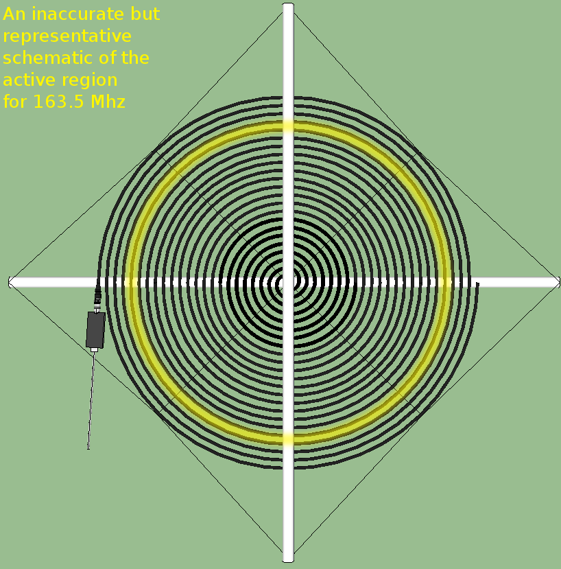
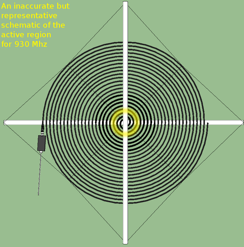
All these inexact calculations of the active region were done assuming the full speed of light in air and the first mode. But in coaxial cable the velocity factor will be lower by some fraction. I am not yet sure if this is important. If it is, the active regions will be smaller in radius.
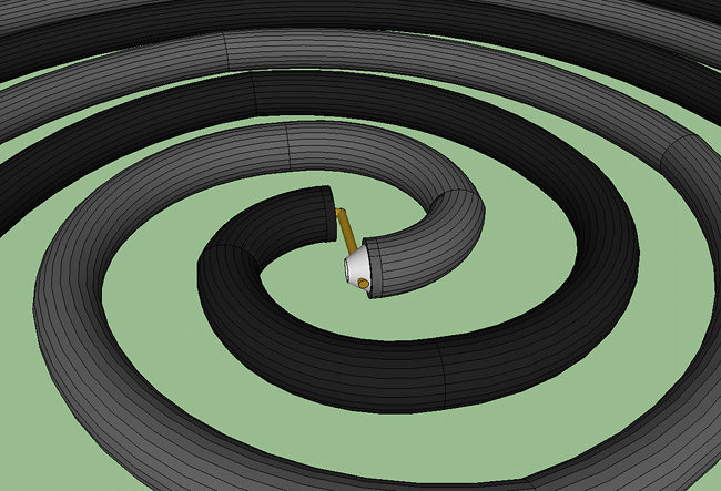
Infinite balun feeds
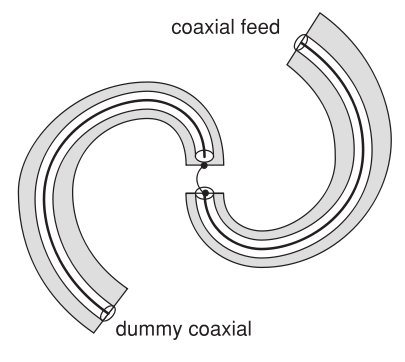
The feed coaxial cable has the rtlsdr dongle on the end. It's inner conductor connects to the outer shield/braid of the second coaxial cable. In this way the outer shield of the second coax acts as one spiral arm and the outer shield of the feed coax acts as the other. The inner surface of the feed coax will act as a transmission line but upon reaching the end the current will flip to the outside of the shield conductor and flow normally. This is called an 'infinite balun'.
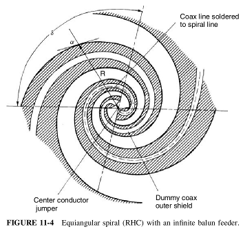
"We can make a balun by using the truncation property of the spiral where the current attenuates rapidly beyond the active region. The balun prevents currents excited on the outside of a coax from reaching the input. In Figure 11-4 we solder the coax feeder to one of the arms. Since the antenna does not radiate in the direction of the expanding arms, it does not excite currents on the structure after the active region; conversely, no currents excited on the structure beyond the active region will reach the input. The coax feeder outer shield becomes part of the antenna. We solder a dummy coax on the second arm to maintain symmetry. Because the balun uses the active region limitation on currents of the antenna, its bandwidth matches that of the antenna."
-- Modern Antenna Design by Thomas A Milligan, 2005, p.557
Feed bridge wire, symmetry and balance?
"In regards to hooking the inner cable of the feed cable to the outer conductor of the second cable, it is important - but for higher frequencies. If you want to extend your bandwidth (in the higher range, not the lower range) - then symmetry in the feed and the more exactness/tightness of the sprial near the feed becomes important. However, if the wavelength of interest is much larger than the dimensions of the feed, then it won't matter too much."
"On the question of the bridge wire: ... Generally it doesn't matter but should be kept short, in general. Again this comes into play at the higher frequencies. But the ratio of the diameters shouldn't matter much."
--bigSteve
c/(2.2 Ghz*4) = 3.4cm
inner radius = 0.5cm
offset of electrical connection from center: ~2mm
I will assume that since 3.4cm is so much larger than inner diameter (1cm) and the ~2mm inbalance in the electrical contact will not matter enough to change the design. To connect the secondary coax, extend the 18 AWG (~1mm) inner wire of the feed coax across the 1cm gap and only expand it to the 5mm outer shield on the secondary coax. The outer shield/braid of the secondary cable can be tightly wrapped to the bridgewire from the feed coax with thin copper wire and then the entire mess soldered with care taken not to touch the secondary coaxial cable's inner conductor.
Since the current decreases exponentially along the spiral hooking the radio receiver directly to the end has little effect on the radiation pattern.
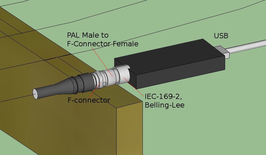
USB Dongle IEC-169-2 connector -> PAL Male to F-Connector Female -> Spiral Antenna coaxial feed arm (darker gray in these sketches).
Construction and materials
Materials
- 2 * 102 cm lengths of 1/2" PVC pipe
- 2 * 13 m lengths of coaxial cable
- 1 * 290 cm length of string
- 100 * plastic zip ties for coax attachment to pvc
- 100 * plastic zip ties for intra-arm spacing
- 1 * 10cm length of thin bare copper wire
Construction
The real result will probably be more wavy and/or square'ish towards the outside of the spiral because of the increasing gap between supports. That is minimized with the string support arms and a chain of zip tie zip tie spacers at the mid-point between pvc tubes.
My design assumes ~0.6cm diameter cable with 0.5cm diameter outer conductor and 1mm diameter inner conductor but use the thickest coaxial cable you can bend smoothly to the desired 0.5cm inner radius. The precise length of the spiral element is closer to 12.83m than 13m. But there's errror and the feed coaxial cable's inner conductor should extend 4cm longer that this to reach the other other coax. Both spirals must have exactly the same length of outer shield conductor acting as the antenna elements.

The outer string, 289cm long, is attached at four places to the outer ring of coaxial cable in the mid-points between the pvc arms. The intention is to put he outer string under tension and pull outwards on the cable towards a more round shape. That outer ring of coax is connected to the next layer in with a zip tie tightened to the correct spacing. And that layer to the next, and so on inward until all are rings of coax and spaced and suspended from the outer string being pulled tight.
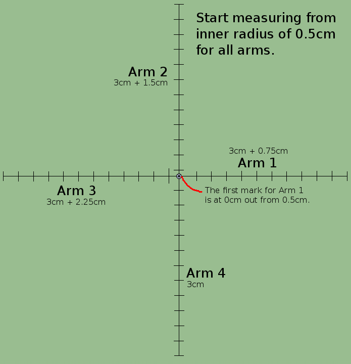
To generate the measurement marks for the coax crossing on the pvc support arms I wrote a perl script. It only works for full of half numbers of turns, and only 4 arms. The other spiral is just the same distances but rotated 180 degrees. So Arm 1 becomes Arm 3, Arm 2 becomes 4, and vice versa.
./archimedesspiralarms.pl r1 0.005 -a 0.03 -t 11.5 -arms 4
Measurements are from arbitrary center point and all units are in meters.
Arm 1
	0.005, 0
	0.035, 1
	0.065, 2
	0.095, 3
	0.125, 4
	0.155, 5
	0.185, 6
	0.215, 7
	0.245, 8
	0.275, 9
	0.305, 10
	0.335, 11
Arm 2
	0.0125, 0
	0.0425, 1
	0.0725, 2
	0.1025, 3
	0.1325, 4
	0.1625, 5
	0.1925, 6
	0.2225, 7
	0.2525, 8
	0.2825, 9
	0.3125, 10
	0.3425, 11
*	0.3575, 11.5
Arm 3
	0.02, 0
	0.05, 1
	0.08, 2
	0.11, 3
	0.14, 4
	0.17, 5
	0.2, 6
	0.23, 7
	0.26, 8
	0.29, 9
	0.32, 10
	0.35, 11
*	0.365, 11.5
Arm 4
	0.0275, 0
	0.0575, 1
	0.0875, 2
	0.1175, 3
	0.1475, 4
	0.1775, 5
	0.2075, 6
	0.2375, 7
	0.2675, 8
	0.2975, 9
	0.3275, 10
	0.3575, 11
Misc notes
"Although Archimedean and exponential spirals have different equations defining them, practice shows that their characteristics do not differ by very much. The Archimedean spiral arm lengths can be long and produce high circuit losses at low frequencies. The wrap angle of an Archimedean spiral changes from a high value in the center to a low value on the outside. The high wrap rate in the center excites more higher-order modes at high frequencies. The low wrap rate at the outer diameter improves pattern shape at low frequencies. Although an exponential spiral has more uniform characteristics over the entire frequency range, an Archimedean spiral is useful."
-- Modern Antenna Design by Thomas A Milligan, 2005, p.545
1,5 - 40 GHz Meander Spiral Antenna Simulation and Design_ Fabrizio Trotta

