Page Sections
- Intro (here)
- Implementation
- Reference
My rtlsdr receiver + w/gnuradio implementation of the 11 GHz VSRT solar interferometer

As far as I understand it, the VSRT design is a subset of intensity interferometer that uses the frequency error between multiple 11 GHz satellite TV "low noise downconverter block" (LNBF) clocks to create a beat frequency in the total power integrated. I am basically copying the MIT Haystack Very Small Radio Telescope (VSRT) but replacing the discrete component integrator and USB video input device with an rtlsdr dongle. The idea is to spend as little on hardware as possible.
With modern LNBF the error between same model parts is about 30 ppm which results in beat frequencies of ~100 KHz at the 10 GHz of the mixers. With this kind of front-end there are no nulls but the fringe modulation can still be read out as variations in count of histogram bins that contain the beat frequency (in the total power fft). This intensity measurement proxy traces out the the envelope of the fringes and varies as a sinc function of distance between antenna. Knowing this and the distance can give you high angular diameter and position measurements of very bright radio sources.
$75 2x 18" satellite dishes w/mounts shipped
$10 2x Ku LNFB (PLL321 S-2, ~30ppm error, RDA3560 w/27Mhz xtal.)
$10 rtlsdr receiver (r820t or e4k, ~30ppm error)
$10 power combiner (cheaper ones work too)
$5 coaxial power injector (LPI 2200)
$20 coaxial power supply (LPI 188PS) + diodes
$20 100ft RG6 quadshield + F connectors
$130 Two Dish Position Motors (HH90)
$60 DVB-S PCI card (Skystar 2, DiSEqC 1.2)
$10 DiSEqC 1.2 switch
$80 PVC, metal stock, drill bits
Historical and other context.
For a detailed mathematical explanation of VSRT see MIT Haystack's VSRT Introduction.
There is also a thread on the Society for Amateur Radio Astronomers list discussing the VSRT design. The more general concept of intensity interferometry, where you correlate total power instead of frequency, was originally developed by Hanbury-Brown & Twiss. Roger Jennison was around too. "The Early Years of Radio Astronomy: Reflections Fifty Years after Janskys Discovery" by W T Sullivan (2005) is an excellent source about Hanbury Brown and Twiss's side of it. The chapter "The Invention and Early Devlopment of The Intensity Interferometer" (pdf) is fascinating. Also see "The Development of Michelson and Intensity Long Baseline Interferometry" (pdf). It covers not only the technical concepts but also historical context, detailed hands-on implementations, and other personal anectdotes. And check out Jennison's book "Radio Astronomy" (1966)) as he invented the process of phase closure which uses a third antenna signal combined mathematically to recover some of the missing phase information. Arranged in a triangle of projected baselines the phase errors cause equal but opposite phase shifts in ajoining baselines, canceling out in the "closure phase". The MIT Haystack groups managed to resolve individual sunspots groups moving across the solar disk using with the technique with the VSRTs.
"An interferometer is an instrument that combines two signals (normally from two detectors) in a manner that the signals interfere to produce a resultant signal. The resultant signal is usually the vector sum of the two signals, but in some cases it is the product or some other mix. The traditional interferometer, usually studied and analyzed in physics courses, combines the two signals in a way that both amplitude and phase information are used. By varying the positions of the two detectors, it is possible to synthesize an effective aperture that is equivalent to the separation of the detectors and to reconstruct the impinging wavefront, thus providing significant information about the extent and structure of the signal source. The traditional phase-sensitive interferometer requires retention of the signal phase at each detector – the phase-sensitive interferometry technique will not be discussed in detail here."
"A special case of the interferometer is the intensity interferometer, which performs an intensity correlation of signals from the two detectors. Although in the intensity interferometer the phase information from the two antennas is discarded, the correlation of the two signals remains useful. Aperture synthesis is not practical, but some important source characteristics may be determined."
I think the VSRT is a special case of intensity interferometer where you don't try to align samples by time after recording. Instead you just look for the baseline distance sinc pattern in total power at the beat frequency of the unsynchronized clocks.
Implementation so far.
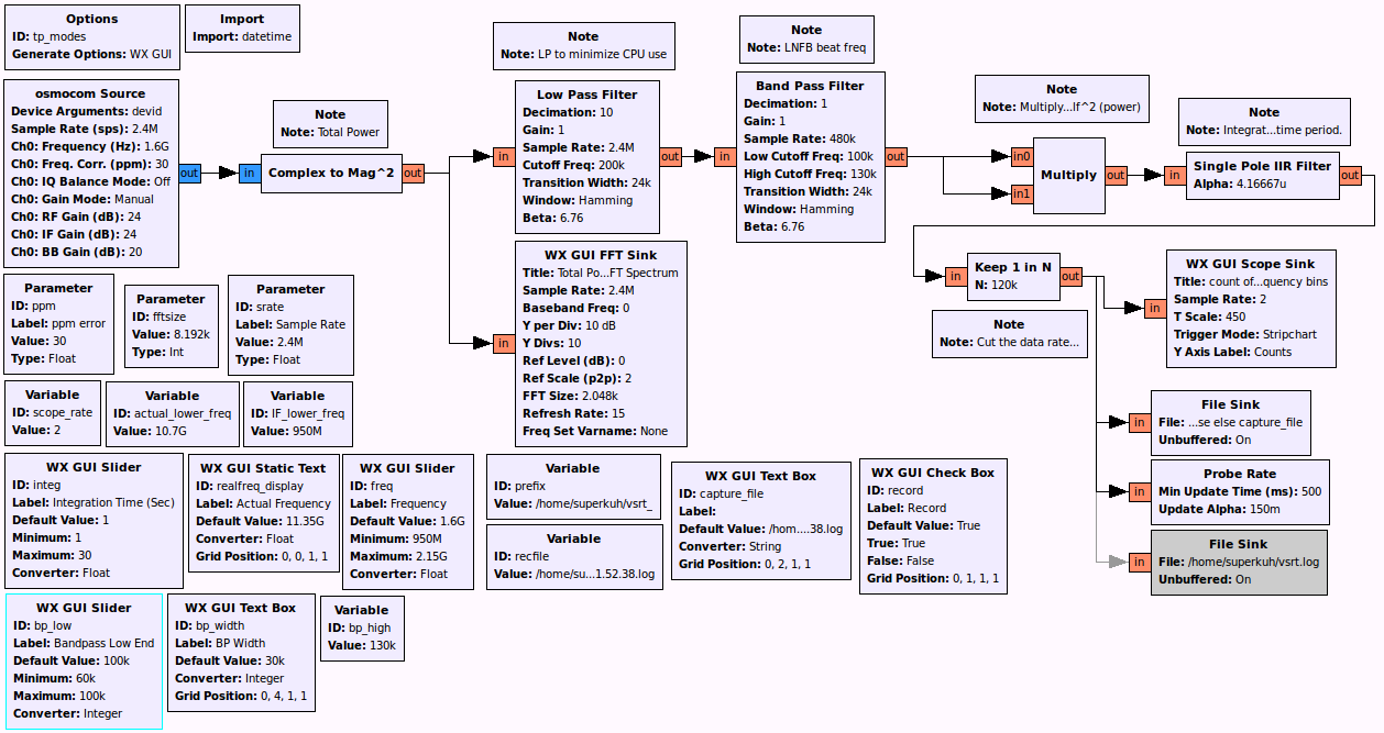
So far I've only done it with manual pointing screwed to a board. The interferometry correlation is done with a satellite tv market stripline power combiner at the intermediate frequency (IF, ~950-1950 MHz) and then an rtlsdr dongle is used to measure the total power of a 2.4 MHz bandwidth of the intermediate frequency range. I use a gnuradio-companion flowgraph to take the total power and then do a fourier transform of the total power. In this fourier transform the fringes show up as a modulation of the count in the FFT bins which correspond to the difference in frequency between the two downconverters. In my case this is about ~100 KHz.
In the Haystack VSRT memos a line drop amplifier, or two, are sometimes put behind the respective LNBF IF coax outputs or the power combiner. With the rtlsdr dongle and relative short (<10m) baselines of RG6 this isn't required.
The GUI allows for setting the exact 2.4 MHz bandwidth of the IF range to sample and the total power FFT bin bandpass to where and what the LNBF beat frequency is. The file name is autogenerated to the format,
prefix + datetime.now().strftime("%Y.%m.%d.%H.%M.%S") + ".log"
The time embedded in the filename is later used by a perl script, vsrt_log_timeplot.pl, which converts and metadata tags the binary records to gnuplot useable text csv format for making PNG plots.
Download
Who else helped
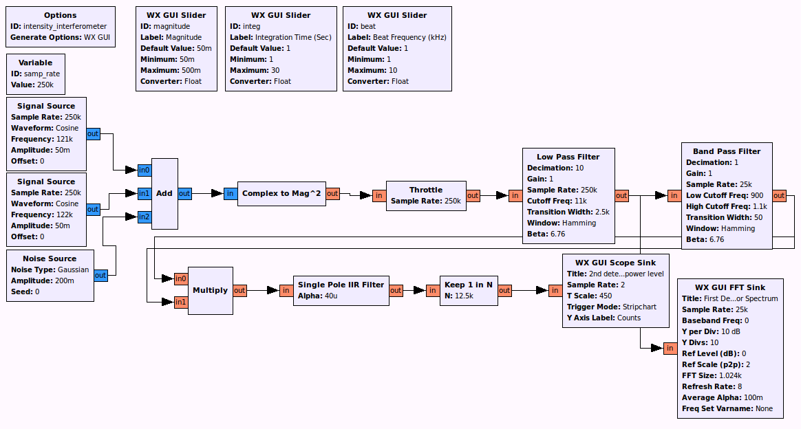
I consulted with patchvonbraun a lot for the software/gnuradio side. He gave me an example of how to use the WX GUI Stripchart and I would not have guessed I needed to square the values from the beat frequency bins after the first squaring for taking total power. He made a generic simulator for dual free running clocks LNBF intensity interferometers. You don't even need to have an rtlsdr device to run it; only an up to date install of gnuradio. It is an easy way to understand how to do interferometry without a distributed clock signal.
patchvonbraun's: simulated-intensity-interferometer.grc
Physical

With this setup on a 1 meter baseline and a intermediate tuning frequency of 1.6 GHz IF (10700 MHz+(1600 MHz−950 MHz)= 11350 MHz) the main beamwidth would be about 70*(c/11GHz)/1m), or 1.9 degrees. This does not resolve the solar disk (~0.5 deg) during drift scans. I have been told that the magnitude goes down in a SINC pattern as you widen the baseline and approach resolving the source but I will not resolve the sun initially. In the VSRT Memos "Development of a solar imaging array of Very Small Radio Telescopes" a computationally complex way to resolve individual action regions is done with a 3rd dish providing "phase closure" in the array on a slanted north-south baseline in addition to the existing east-west baseline. I try to point my dishes so that the Earth is passing the sun through the beam at ~12:09pm (noon) each day. To aid in pointing a cross of reflective aluminum tape is applied center of the dish. This creates a cross of light on the LNBF feed when it is in the dish focal plane and the dish is pointed at the sun. The picture below is from later in the day, the one of the left shows the sun drifting out of the beam as it sets. I made my LNBF holders out of small pieces of wood compression fit in the dish arm. There are grooves for the RG6 coax to fit ground out with a rotary tool. The PVC collars have slots cut in the back with screws going into the wood to set the angle.

The screenshot shows a short run near sunset on an otherwise cloudy day. The discontinuities are me running outside and manually re-pointing the dishes. But it does highlight how the beat frequency of the 2 LNBF varies as they warm up when turned on. It starts down at ~90 KHz but within 10 minutes it rises to ~115 KHz. After it reaches equilibrium the variation is ~ -+1 KHz. I could change the existing 80-120 KHz bandpass to a 110-120 KHz bandpass and have better sensitivity. But that bandwidth is something that has to be found empirically with each LNBF pair and set manually within the GUI for now.
patchvonbraun said it was feasible to identify the frequency bins with the most counts and that there was an example within the simpla_ra code,
"You could even have a little helper function, based on a vector probe, that finds your bin range, and tunes the filter appropriately."
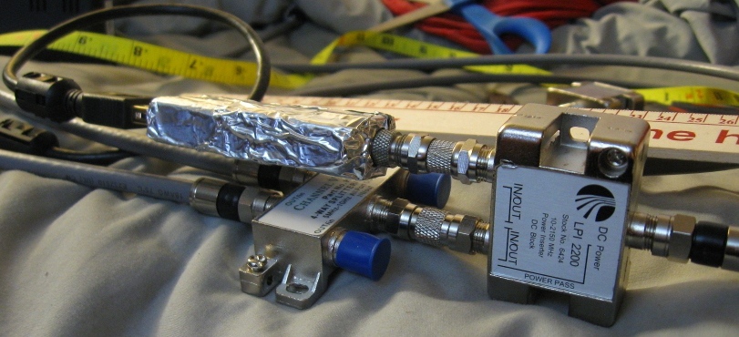
The below close up of indoor testing showing how everything is connected on the rtlsdr side showing the power injector, e4k based rtlsdr (wrapped in aluminum tape), and the stripline based satellite power combiner for correlation. The two rg6 quadshield coaxial lines going from the power combiner to the ku band LNBF are as close to the same length as I could trim them. I use a 1 amp 18v power supply and coaxial power injector to supply power to the LNB and any amplifiers. This voltage controls linear polarization (horiztonal/vertical) and it can be changed by putting a few 1 amp 1N4007 in series with the power line to drop the voltage.
Accessory scripts.
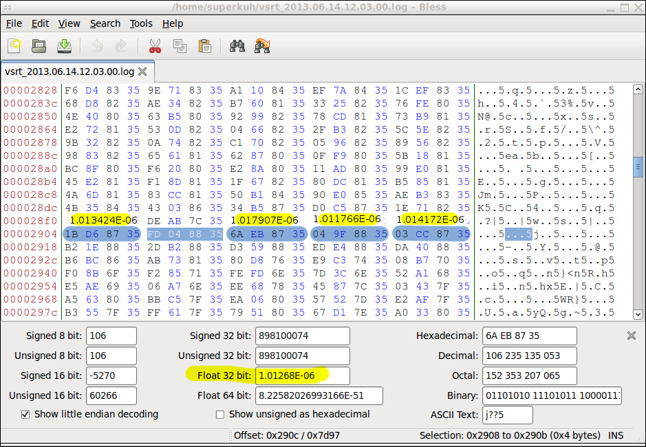
tp-modes.grc produces binary logs that are pretty simple. The count of the LNBF beat frequency bins in the bandpass are saved as floats represented as 4 pairs of hexadecimal. When the integration time is set to the default 1 second then one 4 byte data point is written to the log every 0.5 seconds. I highly recommend not changing this for now. There is no metadata or padding. Here's a screenshot of a run using the utility "bless",
In order to convert the binary logs of 4 byte records into something gnuplot can parse I use a simple perl script,
#!/usr/bin/perl
use warnings;
use strict;

my $data = '/home/superkuh/vsrt_2013.06.13.12.26.47.log';
my $bytelength = 4;
my $format = "f"; # floats (little endian)
my $num_records;

if ($ARGV[0]) {
	$data = $ARGV[0];
} else {
	print "you need to pass the log file path as an argument.";
	exit;
}

open(LOG,"$data") or die "Can't open log.\n$!";
binmode(LOG);

my $i = 0;
until ( eof(LOG) ) {
	my $record;
	my $decimal;
	read(LOG, $record, $bytelength) == $bytelength
		or die "short read\n";
	$decimal = unpack($format, $record);
	printf("$i,\t$decimal\n", $decimal);
	$i++;
}
Now I have the filename which gives the time the gnuradio-companion grc file started running. This is not the time I hit the record button and started logging. The offset is a second or two. Ignoring that, it is possible to use the start time encoded in the log file name to figure out when a particular measurement was taken. To do that I have to know the interval between entries saved to the binary log.
$ date && ls -l /home/superkuh/vsrt_2013.06.14.12.03.00.log && sleep 60 && date && ls -l /home/superkuh/vsrt_2013.06.14.12.03.00.log
Fri Jun 14 13:05:24 CDT 2013
-rw-r--r-- 1 superkuh superkuh 29644 2013-06-14 13:05 /home/superkuh/vsrt_2013.06.14.12.03.00.log
Fri Jun 14 13:06:24 CDT 2013
-rw-r--r-- 1 superkuh superkuh 30124 2013-06-14 13:06 /home/superkuh/vsrt_2013.06.14.12.03.00.log

((30124−29644)/4)/60 = 2

$ date && ls -l /home/superkuh/vsrt_null.log && sleep 60 && date && ls -l /home/superkuh/vsrt_null.logFri Jun 14 13:44:36 CDT 2013
-rw-r--r-- 1 superkuh superkuh 8 2013-06-14 13:44 /home/superkuh/vsrt_null.log
Fri Jun 14 13:45:36 CDT 2013
-rw-r--r-- 1 superkuh superkuh 488 2013-06-14 13:45 /home/superkuh/vsrt_null.log

((488−8)/4)/60 = 2
To know what time a log record corresponds to, take the time from the filename and then add 0.5 seconds * the index of the 4 byte entry in the binary log. This should be possible to write into the until loop so it outputs time instead of just index $i. The below example is a hacky version of my log parser that does just this. Here's an example output.
# UTC Epoch	# Beat Freq Bins
1371229380.0,	1.38292284646013e-06
1371229380.5,	1.37606230055098e-06
1371229381.0,	1.374015937472e-06
1371229381.5,	1.366425294691e-06
1371229382.0,	1.35845414206415e-06
1371229382.5,	1.36476899115223e-06
1371229383.0,	1.36480070977996e-06
1371229383.5,	1.36444589315943e-06
1371229384.0,	1.35775212584122e-06
1371229384.5,	1.36395499339415e-06
1371229385.0,	1.35322613914468e-06
1371229385.5,	1.36412847950851e-06
1371229386.0,	1.36531491534697e-06
1371229386.5,	1.3664910056832e-06
1371229387.0,	1.36144888074341e-06
1371229387.5,	1.35596496875223e-06
1371229388.0,	1.35830066483322e-06
1371229388.5,	1.3654090480486e-06
1371229389.0,	1.358990175504e-06
1371229389.5,	1.37098015784431e-06
1371229390.0,	1.387945303577e-06
1371229390.5,	1.38286770834384e-06
1371229391.0,	1.36734763600543e-06
1371229391.5,	1.36036248932214e-06
...
#!/usr/bin/perl
use DateTime;
use warnings;
use strict;

# The simplest possible gnuplot plot using this program's output.
# ./vsrt_log_timeplot.pl /home/superkuh/vsrt_2013.06.14.12.03.00.log > whee2.log
# gnuplot> plot "./whee2.log" using 1:2 title "VSRT Test" with lines

my $data = '/home/superkuh/vsrt_2013.06.13.12.26.47.log';
my $bytelength = 4;
#my $format = "V"; # oops, not this unsigned 32 bit (little endian)
my $format = "f"; # float
my $num_records;

if ($ARGV[0]) {
	$data = $ARGV[0];
} else {
	print "you need to pass the log file path as an argument.";
	exit;
}

my $dt; # declare datetime variable globally
extracttime($data); # $dt now has date object.

open(LOG,"$data") or die "Can't open log.\n$!";
binmode(LOG);

my $i = 0;
until ( eof(LOG) ) {
	my $record;
	my $decimal;
	read(LOG, $record, $bytelength) == $bytelength
		or die "short read\n";

	$decimal = unpack($format, $record);

	# This is a stupid/fragile way to deal with datetime
	# not having enough precision. It only works if the
	# record to record interval is always 0.5 seconds.
	my $recordtime = $dt->epoch();
	if (0 == $i % 2) {
		printf("$recordtime.0,\t$decimal\n", $decimal);
	} else {
		printf("$recordtime.5,\t$decimal\n", $decimal);
	}

	$dt->add( nanoseconds => 500000000 );
	$i++;
}

sub extracttime {
	my $timestring = shift;
	# /home/superkuh/vsrt_2013.06.13.12.26.47.log
	$timestring =~ /(\d{4}\.\d{2}\.\d{2})\.(\d\d\.\d\d\.\d\d)/;
	my $year_month_day = $1;
	my $time = $2;

	my ($year,$month,$day) = split(/\./, $year_month_day);
	$time =~ s/\./:/g;
	my ($hour,$minute,$second) = split(/:/, $time);

	$dt = DateTime->new(
		year       => $year,
		month      => $month,
		day        => $day,
		hour       => $hour,
		minute     => $minute,
		second     => $second,
		time_zone  => 'America/Chicago',
	);

	$dt->set_time_zone('UTC');
	return 1;
}
Now I just have to make up a good gnuplot format and integrate the calls into the perl script.
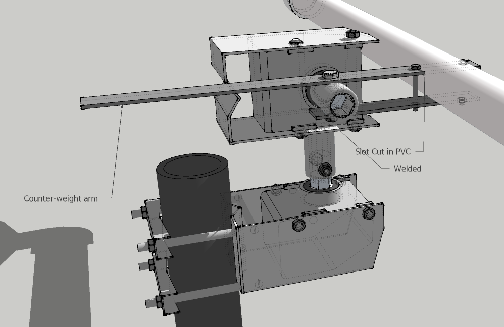
Computer controlled pointing, mechanical and software differences

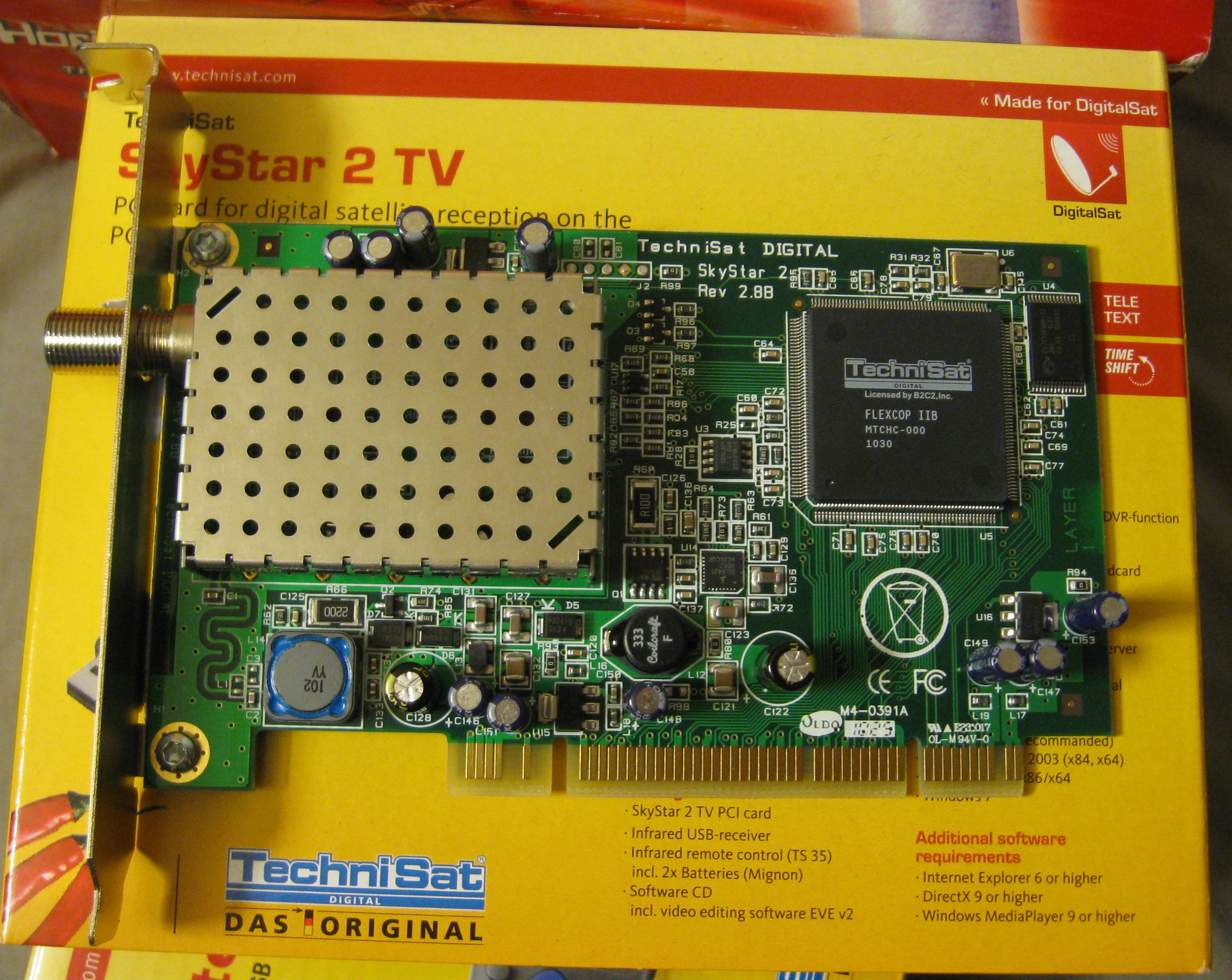
Manually repositioning the dishes swamps out the signal of interest as the target leaves the beamwidth. For any decent measurements I need computer controlled pointing. This means the Haystack idea of two coupled Diseqc 1.2 compatible motor positioners mounted one on the other. In their design both dishes are mounted on a single PVC tube hooked to one of the positioners with a metal extension. My satellite dish mounts can't rotate like theirs so I'll have to modify this design a bit. They use a serial relay to "push" the buttons on a physical Diseqc 1.2 motor controller remote. That seemed a bit convoluted to me. I bought a SkyStar2 DVB-S pci card and under linux send raw Diseqc commands out by calling xdipo which accesses the linux DVB interface. It has both a GUI and cli interface. Unfortunately xdipo cannot send through Diseqc switches. I had to add manual motor commands to tune-s2 which did support switches but not manual motor commands. This version which supports manual stepping mode is available at https://github.com/superkuh/tune-s2-stepping.
Another alternative Diseqc motor controller I didn't persue would be using a 192 KHz USB soundcard and the DiSEqC Audio Generator software from Juras-Projects. The documentation for the hardware side of the audio generator is 404 now, but Juras responded to an email of mine with the schematics attached.
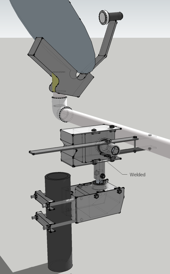
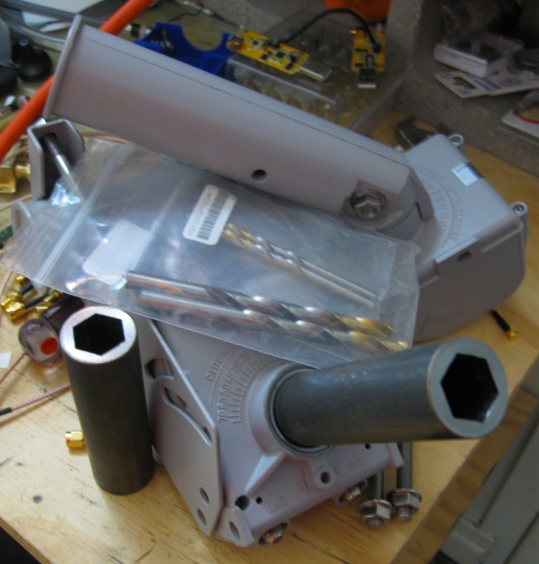
Since the bent motor shafts that came will my motors looked really difficult to drill through I thought I'd use straight hex holed shafts to make everything mechanically simpler. I found http://www.reidsupply.com/sku/HHS-18/ and ordered a couple. Unfortunately my measurements of the dish motor shaft flat-to-flate size were off. The Reid hex holed shaft hole is just a tiny bit too large. This was easily fixed by wrapping a couple turns of masking tape around the shaft to increase the diameter. This is often how fishing rod handles are made. I also encountered this construction technique on Jarrod Kinsey's CO2 laser pages.
The hardest part of all this is drilling an 8mm hole precisely normal to the curved outside surface of the hex hole shaft. The first step is to flatten the area with a hand file. This took me about 10 minutes. I had previously ordered and received two carbide drill bits, one small to sub-drill the intial hole and then one 8mm for the final hole. A drill press and small vice are quired to actually drill the holes. And even then it's really tricky. My first two attempts resulted in holes not quite normal to the surface of the hex flat. I could only use roll or taper pins to secure the shaft. Luckily I bought 2x shafts just in case.
I also had to drill 4 additional 8mm holes in the 2x satellite dish motor mounts to make holes for level mounting instead of at a tilt. The VRST guys got lucky with their sat motor mounts having a long slot.
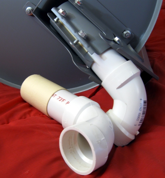
The diameter of easily available PVC is slightly to small for the dish mounting clamp. This is remedied like the motor shafts; by wrapping wide masking tape to size and optionally epoxy coating/sanding it.
The dish motors used in the VSRT project were Stab HH90. These have come down in cost since the VSRT memos were written and are still widely available.
 065	Stab HH90 dish pointing motor #1
 065 	Stab HH90 dish pointing motor #2
$130 total
In order to control these motors a system to send DISEqC 1.2 commands is needed. The first option would be to faithfully replicate the VSRT implementation. They do it in a rather roundabout way but at least it is tested and known to work with their software. Unfortunately the specific hardware used has become rare, is mostly shipped from overseas, or is expensive.
 045	STAB MP01 Positioner Control #1
 045	STAB MP01 Positioner Control #2
 080	WTSSR-M Serial port Solid State Relay
 000	VSRT Java software (windows)

 030	Two 5" x 9" x 0.125" thick steel plates
 020	Two 15" x 1" x 0.125" thick aluminum counterweight arms
 020	Shipping for the metal parts.
My chosen method of HH90 motor control is a single DVB-S card under linux with DVB API 5.x w/ my modified tune-s2 and optionally xdipo. This can be combined with a DiSEqC switch to scale to control of multiple motors relatively cheaply. I do sun alt-az position calculation by using a small pysolar python script. I have not yet completed the scripts to turn alt-az positions of the sun at my location into motor step commands. Hopefully I can use some of the USAL fuctions in tune-s2 for that.
 066	Skystar 2 HD pci card
 010	DiSEqC switch
 000	tune-s2 and xdipo DVB control software (linux)

 020	.753" Hex-Holed Sleeve
 010	5" wide masking tape
 020	Two 15" x 1" x 0.125" aluminum counterweight arms
Both require PVC pipe, tools like drills, 8mm drill bits and smaller sub-drill bit, hand saws, files, and potentially a welder (though liberal J-B Weld would probably work).
Diseqc switches problems and solutions.
It turns out that xdipo alone cannot deal with motors behind Diseqc switches. This means it can only control one Diseqc motor at once. Controlling two would require 2x Skystar 2 pci cards. Luckily there are other options. CrazyCat's tune-s2 supports Diseqc switches and addressing. It normally only provides for motor commands using the USAL system which isn't too helpful. But I was able to modify the code to support manual motor position commands while retaining the switch support. xdipo could still be used in theory by calling tune-s2 to set the Diseqc switch to the appropriate port/motor and then calling xdipo as normal. But it is easier to just use the modified tune-s2 for everything.
This gutted version of tune-s2 for manual motor commands is available at:
https://github.com/superkuh/tune-s2-stepping
The functions I added are basically just look up arrays with Diseqc bus commands for different steps in the clockwise or counter-clockwise directions. In Diseqc the packets have 4 sections. Check out the Diseqc Bus Functional Specification (pdf) for a better explanation with more detail.

The first, "Framing" byte represent if the command is from the receiver or diseqc device and wether it needs a reply. For my table these are all just "EO" which means it's a packet from the receiver with no response required. Most commands are EO but it goes up to E7.
The second, "Address" specifies which types of Diseqc devices should listen (ex: LNB, switch, motor, polarizer). For motors this is "32"
The third is "Command". This is a huge list of values of which only "68" and "69" are relevant. They are "Drive Motor East" and "Drive Motor West" respectively. The "Command" byte is only relevant to their specific devices specified via the "Address" byte.
The remaining bytes of the packet are "Data" and how they're interpreted depends on the "Command" bytes specifying a specific type of command. For motor movement there are three options. "00" makes the motor turn until a Diseqc stop command is sent. The second mode is positive values for the bytes, "01" to "7F". They represent an amount of time to turn the motor. Or by specifying negative byte values "80" to "FF" the motor is rotated a number of steps. This last is best and detailed in the Positioner Application Note (pdf) with an excerpt below,
The number of steps to make is given by the additional count needed to make the parameter byte reach zero (or overflow to zero if the byte is considered as unsigned). Thus the byte 'FF' (hexadecimal) requests only one step, 'FE' two steps, and for example 'F9' requests 7 steps.
With my motors each step corresponds to about 0.1 deg. Using this information I made up a table of Diseqc packets for each rotation direction.
struct dvb_diseqc_master_cmd step_east[] =
{
	{ { 0xe0, 0x31, 0x68, 0xFF, 0x00, 0x00 }, 4 },  // Drive Motor West 1 step
	{ { 0xe0, 0x31, 0x68, 0xFE, 0x00, 0x00 }, 4 },  // Drive Motor West 2 step
	{ { 0xe0, 0x31, 0x68, 0xFD, 0x00, 0x00 }, 4 },  // Drive Motor West 3 step
	{ { 0xe0, 0x31, 0x68, 0xFC, 0x00, 0x00 }, 4 },  // Drive Motor West 4 step
	{ { 0xe0, 0x31, 0x68, 0xFB, 0x00, 0x00 }, 4 },  // Drive Motor West 5 step
	{ { 0xe0, 0x31, 0x68, 0xF6, 0x00, 0x00 }, 4 },  // Drive Motor West 10 step
	{ { 0xe0, 0x31, 0x68, 0xEC, 0x00, 0x00 }, 4 },  // Drive Motor West 20 step
	{ { 0xe0, 0x31, 0x68, 0xE2, 0x00, 0x00 }, 4 },  // Drive Motor West 30 step
	{ { 0xe0, 0x31, 0x68, 0xD8, 0x00, 0x00 }, 4 },  // Drive Motor West 40 step
	{ { 0xe0, 0x31, 0x68, 0xCE, 0x00, 0x00 }, 4 },  // Drive Motor West 50 step
	{ { 0xe0, 0x31, 0x68, 0x9C, 0x00, 0x00 }, 4 }   // Drive Motor West 100 step
};

struct dvb_diseqc_master_cmd step_west[] =
{
	{ { 0xe0, 0x31, 0x69, 0xFF, 0x00, 0x00 }, 4 },  // Drive Motor West 1 step
	{ { 0xe0, 0x31, 0x69, 0xFE, 0x00, 0x00 }, 4 },  // Drive Motor West 2 step
	{ { 0xe0, 0x31, 0x69, 0xFD, 0x00, 0x00 }, 4 },  // Drive Motor West 3 step
	{ { 0xe0, 0x31, 0x69, 0xFC, 0x00, 0x00 }, 4 },  // Drive Motor West 4 step
	{ { 0xe0, 0x31, 0x69, 0xFB, 0x00, 0x00 }, 4 },  // Drive Motor West 5 step
	{ { 0xe0, 0x31, 0x69, 0xF6, 0x00, 0x00 }, 4 },  // Drive Motor West 10 step
	{ { 0xe0, 0x31, 0x69, 0xEC, 0x00, 0x00 }, 4 },  // Drive Motor West 20 step
	{ { 0xe0, 0x31, 0x69, 0xE2, 0x00, 0x00 }, 4 },  // Drive Motor West 30 step
	{ { 0xe0, 0x31, 0x69, 0xD8, 0x00, 0x00 }, 4 },  // Drive Motor West 40 step
	{ { 0xe0, 0x31, 0x69, 0xCE, 0x00, 0x00 }, 4 },  // Drive Motor West 50 step
	{ { 0xe0, 0x31, 0x69, 0x9C, 0x00, 0x00 }, 4 }   // Drive Motor West 100 step
};
For addressing specific ports of the Diseqc switch tune-s2's normal functions are used. They are called before the motor position commands are sent. Usage of the modified tune-s2 is pretty simple. The only differences are two new cli switches and not needing to give it tuning parameters.
-step-east
-step-west
They each take any value from 0 to 10 like,
./tune-s2 -step-west 0 -committed 1
This would cause the satellite dish motor on port 1 of the Diseqc switch to step 1 position counter-clockwise. To send the same command of stepping 1 position counter-clockwise to the other motor,
./tune-s2 -step-west 0 -committed 2
The stepping argument values 0 through 10 are mapped on a fairly arbitrary set of actual steps. This results from just doing array index look ups in the above packet tables,
0->1
1->2
2->3
3->4
4->5
5->10
6->20
7->30
8->40
9->50
10->100
http://www.satnigmo.com/2254/how-to-configure-emp-centauri-diseqc-switches/
Calculating solar position and using that to decide how many steps to step per axis
Figuring out where the sun is in the sky in terms of an alt-az format is made simple by pysolar. Figuring out how to turn that position into sequences of steps on the motors is much, much harder.
#! /usr/bin/env python
import Pysolar
import datetime
d = datetime.datetime.utcnow()
lat = 40.0
long = -90.0
sol_alt = Pysolar.GetAltitude(lat, long, d)
sol_long = Pysolar.GetAzimuth(lat, long, d)
print sol_alt
print sol_long
These values are relative to the pysolar reference frame which is given by their diagram,
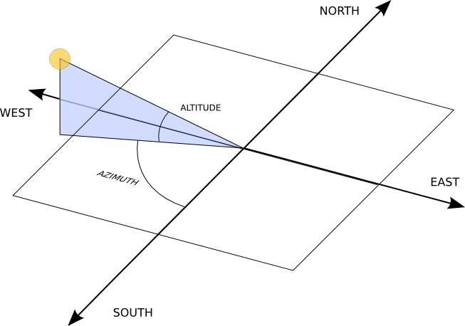
$ ./solpos.py
41.4925424732
-35.8472087363
My setup is pointed directly south. So for this example time that means I need to calculate the number of steps required to turn the (top) altitude motor 41.5 up from level and the (bottom) azimuth motor 35.8 degrees to the left (east).
[comment on this post] Append "/@say/your message here" to the URL in the location bar and hit enter.

